Inserting installation type one-way speed regulating valve

A one-way speed regulating valve, a cartridge technology, applied in the direction of control valve, safety valve, balance valve, etc., can solve the problems of difficult manufacturing, complex structure, large volume of the speed regulating valve, etc., and achieve simple structure and small volume. Effect

Active Publication Date: 2018-04-13
山东禧龙石油装备有限公司
View PDF9 Cites 2 Cited by
  • Summary
  • Abstract
  • Description
  • Claims
  • Application Information

AI Technical Summary

Problems solved by technology

Although this one-way speed control valve can realize one-way stepless speed regulation of the working parts, it needs a higher pressure to open the slide valve when the working cylinder returns quickly, so it is not suitable for use in low-pressure circuits.
At the same time, because the throttling mechanism and the slide valve are separately arranged in the intersecting hole in the valve body, the speed regulating valve has a large volume and a very complicated structure, and requires several more process holes, which increases the external leakage link and is difficult to manufacture. The cost is high, and it is limited by the huge shape during use, so it cannot be used in a small installation space

Method used


Image

  • Inserting installation type one-way speed regulating valve
  • Inserting installation type one-way speed regulating valve
  • Inserting installation type one-way speed regulating valve

Examples


Embodiment Construction

[0020] The present invention will be further described in detail below in conjunction with the accompanying drawings and embodiments.

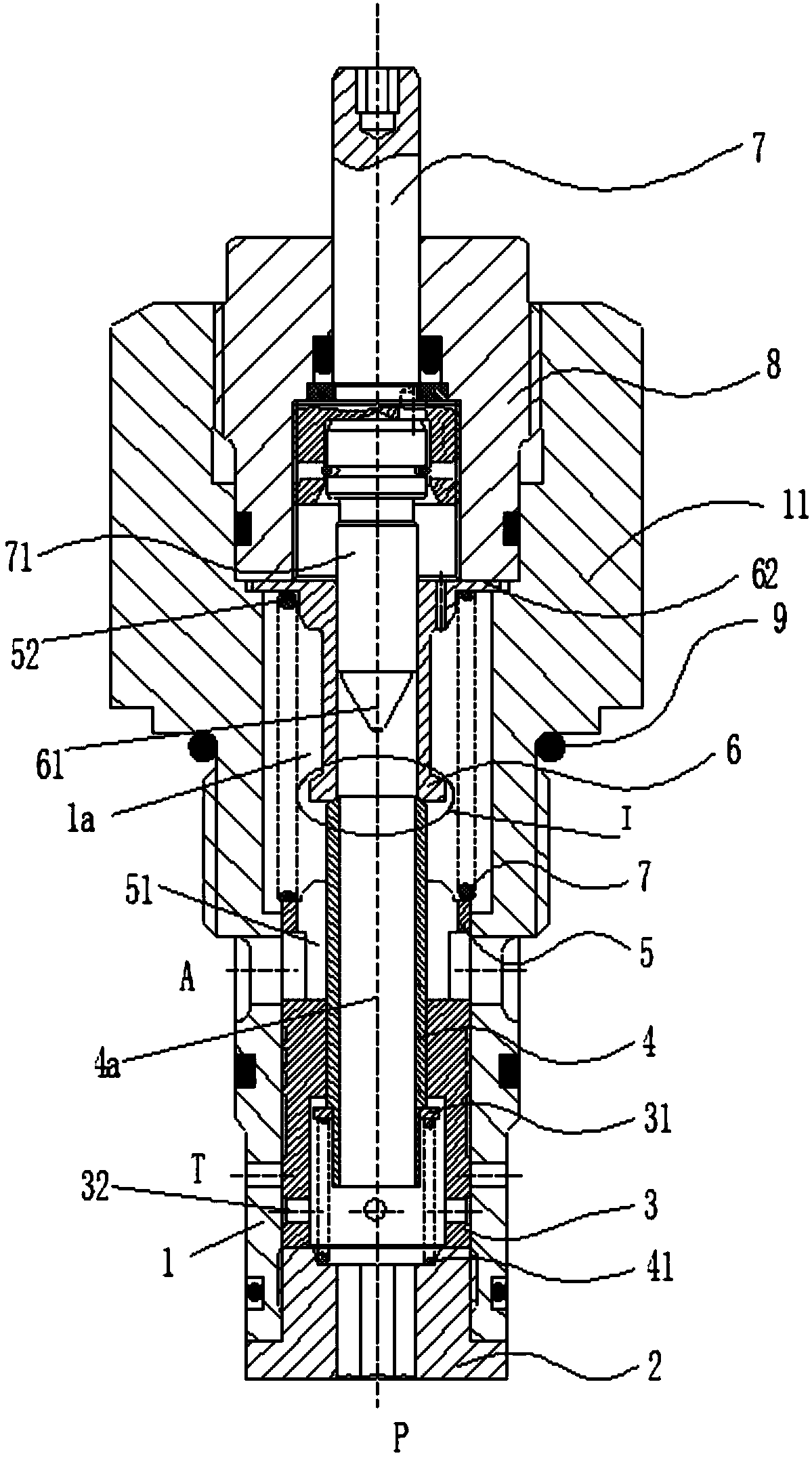
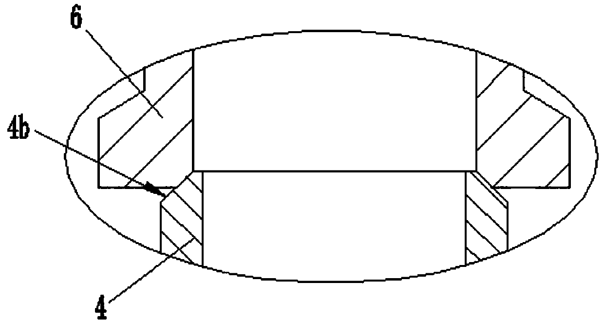
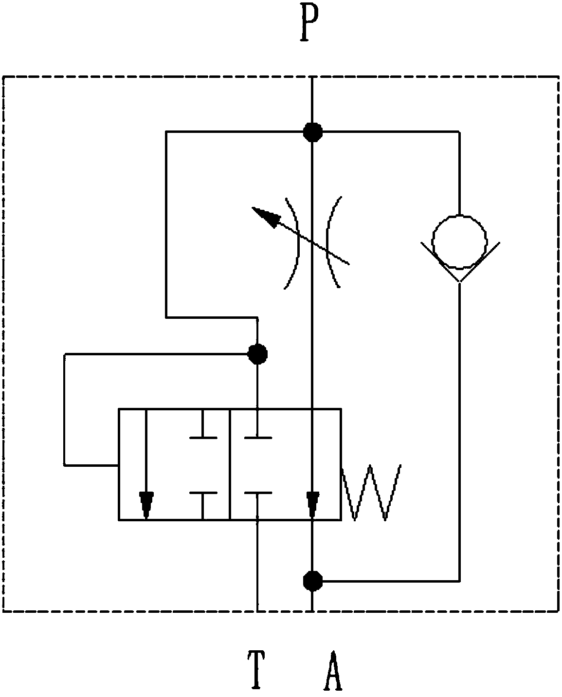
[0021] Such as Figure 1 to Figure 2 Shown is the structural representation of the present invention,

[0022] The reference signs are: P port, A port, T port, valve body 1, flow chamber 1a, external thread 11, screw plug 2, pressure compensating valve core 3, gasket 31, through hole 32 one-way valve core 4. Flow hole 4a, slope 4b, first spring 41, bushing 5, flow groove 51, second spring 52, throttle valve sleeve 6, throttle groove 61, limit edge 62, adjustment rod 7, adjustment Cover 8, sealing ring 9.

[0023] Such as Figure 1 to Figure 2 as shown,

[0024] A plug-in one-way speed regulating valve, including a valve body 1, the lower end of the valve body 1 is provided with a screw plug 2, the center of the screw plug 2 is provided with a P port, and the side wall of the valve body 1 is provided with an A port and T port, T port is lo...


PUM


Abstract

The invention discloses an inserting installation type one-way speed regulating valve. A valve body is included; the lower end of the valve body is provided with a screw plug; the center of the screwplug is provided with a port P; the side wall of the valve body is provided with a port A and a port T; a pressure compensating valve element is arranged in the valve body; the side wall of the lowerportion of the pressure compensating valve element is provided with a through hole; the pressure compensating valve element slides upwards, and can control the opening degree of the port A and communicate the port P with the port T through the through hole; the center of the pressure compensating valve element is provided with a one-way valve element; the center of the one-way valve element is provided with a through flow hole; a first spring is arranged between the one-way valve element and the screw plug; a bush is arranged above the pressure compensating valve element, and is provided witha through flow groove communicated with a port B; a throttling valve sleeve is arranged in the upper portion of the valve body; the lower end of the throttling valve sleeve is provided with a valve port matched with the one-way valve element; a through flow cavity is formed between the outer wall of the throttling valve sleeve and the inner wall of the valve body; the throttling valve sleeve is provided with a throttling groove communicated with the through flow cavity; and a second spring is arranged between the bush and the throttling valve sleeve. The inserting installation type one-way speed regulating valve has the beneficial effects of being simple and compact in structure and small in volume, and flow can be kept constant by means of pressure compensating.

Description

technical field [0001] The invention relates to the technical field of speed control valve manufacturing, in particular to a plug-in one-way speed control valve. Background technique [0002] The one-way speed control valve is widely used in the speed control of the mechanical hydraulic system, and its function is to realize the one-way stepless speed regulation of the working parts irrelevant to the load; the existing traditional one-way speed control valve mainly includes the valve body, the adjustment handwheel , flow adjustment rod, throttle spool, slide valve, adjusting screw seat and spring seat. [0003] The hydraulic oil enters the throttling cavity from the pump station through the oil inlet passage, and the throttling mechanism composed of the throttling valve core, the flow adjustment rod, the adjustment handwheel and the adjustment screw seat, after steplessly adjusting the flow rate, flows through the oil outlet passage into the working oil cylinder, so that th...

Claims


Application Information

Patent Timeline
Patent Type & Authority Applications(China)
IPC IPC(8): F16K15/02F16K17/22
CPCF16K15/025F16K17/22
Inventor 陈艳艳
Owner 山东禧龙石油装备有限公司
Why Eureka
Try Eureka