Throttling device for high pressure water-feeding pump of industrial boiler

A throttling device and industrial boiler technology, which is applied in the direction of water supply control, preheating, steam generation, etc., can solve the problems of pump impeller impact, large water supply pressure changes, and unstable steam and electricity loads, so as to ensure stability and improve Efforts to improve the effect of safe and economical operation

Inactive Publication Date: 2013-05-15
MCC MEILI CLOUD COMPUTING IND INVESTMENT CO LTD
View PDF4 Cites 0 Cited by
  • Summary
  • Abstract
  • Description
  • Claims
  • Application Information

AI Technical Summary

Problems solved by technology

The current adjustment method is to use the recirculation primary and secondary valves installed in the water supply outlet pipes. However, due to the unstable steam and electricity load of the self-owned power plant and frequent adjustments of the boiler, the spool of the recirculation valve is under high temperature and high pressure water supply pressure. Abrasion occurs under flushing, internal leakage increases, and the adjustment effect is poor. In order to ensure the normal operation of the boiler feed water pump, the primary and secondary recirculation valves are frequently replaced. After replacement, the feed water pressure changes greatly when the boiler is adjusted. The body impeller causes serious impact, which seriously restricts the output of the feed water pump. When the boiler is running at low load, the required feed water flow rate is small, and the internal leakage of the valve cannot be adjusted, resulting in high feed water pressure, which will cause certain unsafe conditions for boiler equipment and pipelines. factors, while increasing plant power consumption
When the boiler is running at high load, the required feedwater flow is large, but due to the large internal leakage of the recirculation valve, it still cannot meet the output of the feedwater pump when adjusted to the limit, resulting in a drop in the feedwater pressure required by the boiler and affecting the safe operation of the boiler. Under certain circumstances, in order to ensure the safe operation of the boiler equipment, it is necessary to start another feed water pump, which increases the power consumption of the plant and increases the cost

Method used


Image

  • Throttling device for high pressure water-feeding pump of industrial boiler

Examples


Embodiment Construction

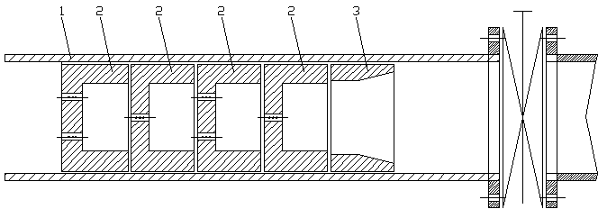
[0008] like figure 1 As shown, the throttling device of the industrial boiler high-pressure feed water pump of the present invention includes a throttling straight pipe 1, and the end face of the throttling straight pipe 1 is equipped with a throttling nozzle 3, and several nozzles are installed in an internal staggered arrangement at an angle of 45° or 90°. Throttle orifice 2.

[0009] During production, the throttling nozzle 3 is first welded to the end face of the throttling straight pipe 1, and then the throttling orifice plates are staggered in turn and installed inside the throttling straight pipe 1 at an angle of 45° or 90°, and the finished throttle The device is welded in front of the primary recirculation door of the outlet pipe of the boiler feed water pump.


PUM


Abstract

The invention relates to a throttling device for a high pressure water-feeding pump of an industrial boiler. The throttling device for the high pressure water-feeding pump of the industrial boiler is characterized by comprising a throttling straight pipe, a throttling nozzle installed on an end face of the throttling straight pipe, and a plurality of throttling orifice plates installed in the throttling straight pipe with a 45-degree angle or a 90-degree angle in a staggered mode. The throttling device for the high pressure water-feeding pump of the industrial boiler is installed in front of a first recycling door of a boiler water-feeding pump outlet pipeline, so that output force of a boiler water-feeding pump can be effectively improved, the water amount can be well throttled, water-feeding pressure needed by the boiler is met, and stability of water feeding of the boiler is guaranteed. The operation number of the first recycling door and a second recycling door when the boiler is normally adjusted is reduced, and safe and economical operation of a boiler unit is improved.

Description

technical field [0001] The invention relates to a throttling device for a high-pressure feed water pump of an industrial boiler, which is especially suitable for fields where the frequent adjustment of steam boilers in self-provided thermal power plants results in obvious changes in the output of the feed water pump. Background technique [0002] During the operation of the boiler equipment, since the reciprocating cycle of the steam-water system is carried out at all times, maintaining the balance of the boiler steam-water is the prerequisite for ensuring the safe operation of the boiler equipment, so the stability of the boiler feed water must be ensured. The high-pressure feed water pump is the main equipment for providing water to the boiler. Due to frequent changes in the steam and electricity load supplied by the thermal power plant to the external grid, the boiler load is also constantly changing, which makes the boiler adjustment more frequent. In the boiler adjustmen...

Claims


Application Information

Patent Timeline
IPC IPC(8): F22D5/00
Inventor 周军龙刘海涛王学军张金霞卢元庆
Owner MCC MEILI CLOUD COMPUTING IND INVESTMENT CO LTD
Why Eureka
Try Eureka