Digital textile printing high-speed output equipment

An output device and high-speed technology, applied in typewriters, printing, etc., can solve the problems of reduced production efficiency, printing quality, and low efficiency, and achieve the effect of improving production efficiency

Inactive Publication Date: 2013-09-11
朴名焕
View PDF7 Cites 0 Cited by
  • Summary
  • Abstract
  • Description
  • Claims
  • Application Information

AI Technical Summary

Problems solved by technology

[0005] On the other hand, for the thermal printing (bubble inkjet method) technology used in high-speed printing, since multiple dye barrels are used to move back and forth along the width direction of the dyed object such as cloth (the direction perpendicular to the direction of cloth travel), press The method of printing in a certain interval or line by line is not only slow in printing speed, but also low in efficiency, and does not have a suitable device for cooling the dye barrels that generate heat during high-speed printing, so it is not suitable for long-term printing (or printing ), in order to solve the heat release problem of the dye tank, only intermittent operations can be carried out, which greatly reduces the production efficiency
[0006] In addition, the dye barrel adopts a reciprocating structure, so it is difficult to accurately determine the initial position of the dye injection position, so errors are prone to occur during speed control. If such errors occur, it will be due to inaccurate dye injection positions. Cause printing focus to be different, reduce quality
In addition, for the high-speed printing method that supports bidirectional printing, there will be errors in the printing position due to the separation of the connecting part, which will reduce the printing quality.
[0007] In addition, due to the smooth operation of the motor and the limitations of the injection of the spray gun, and the dye barrel is a mobile structure, the accuracy is reduced, causing the printing head to touch or wipe the dyed object, so that the printing head hangs on the dyed object. The tearing of the dyed object, if serious, will not only cause damage to the dye barrel, but also cause impurities, air bubbles, etc.

Method used


Image

  • Digital textile printing high-speed output equipment
  • Digital textile printing high-speed output equipment
  • Digital textile printing high-speed output equipment

Examples


Embodiment Construction

[0047] In the following description, the same components in the drawings are marked with the same symbols as much as possible, and at the same time, in order to avoid obscuring the central idea of ​​the present invention, detailed descriptions of related basic structures and functions are omitted.

[0048] The articles to be dyed that can be outputted at high speed according to the present invention include various types of fabrics, papers, and fabrics, etc., and are collectively referred to as "the articles to be dyed" hereinafter for the convenience of description.

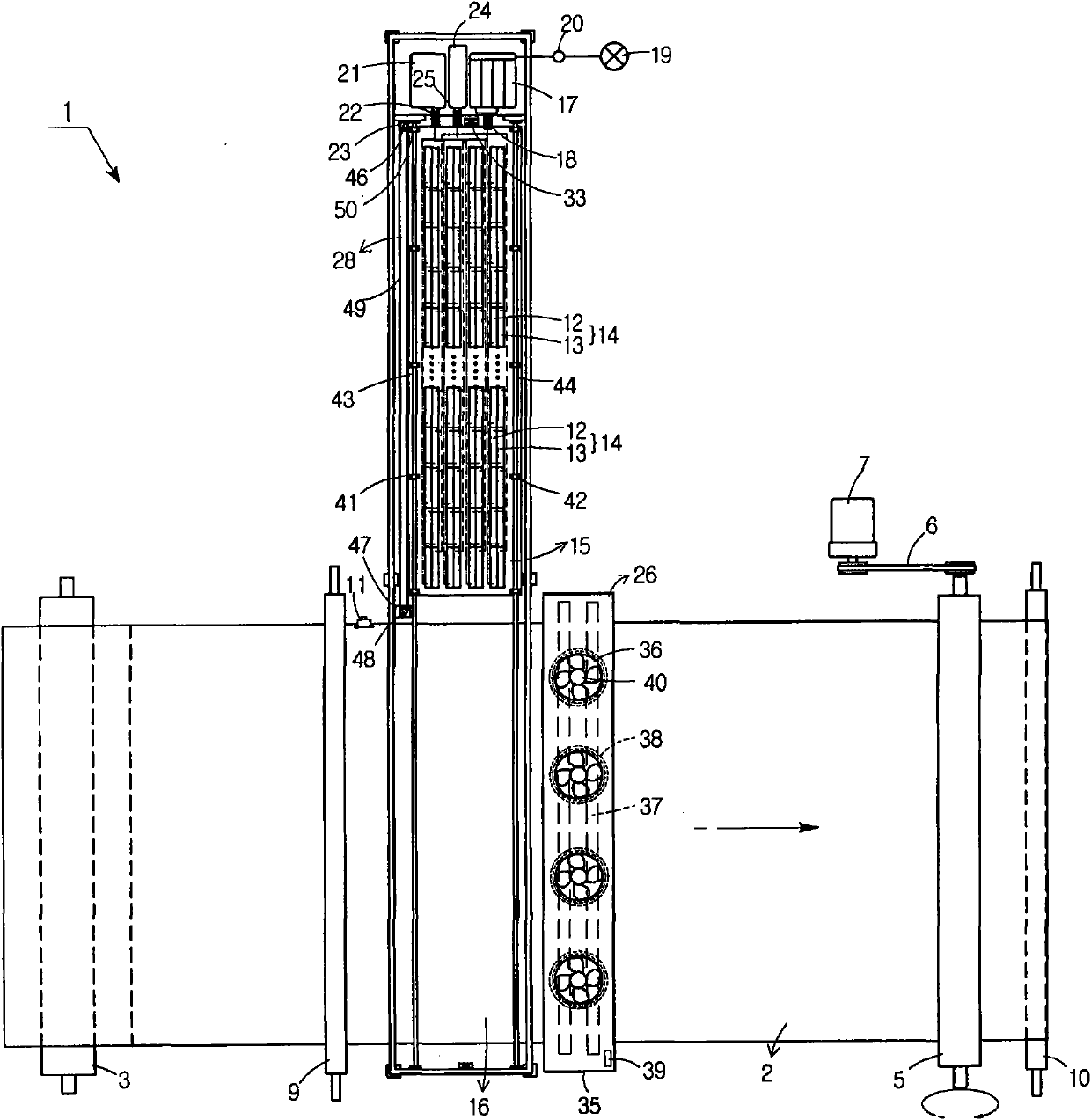
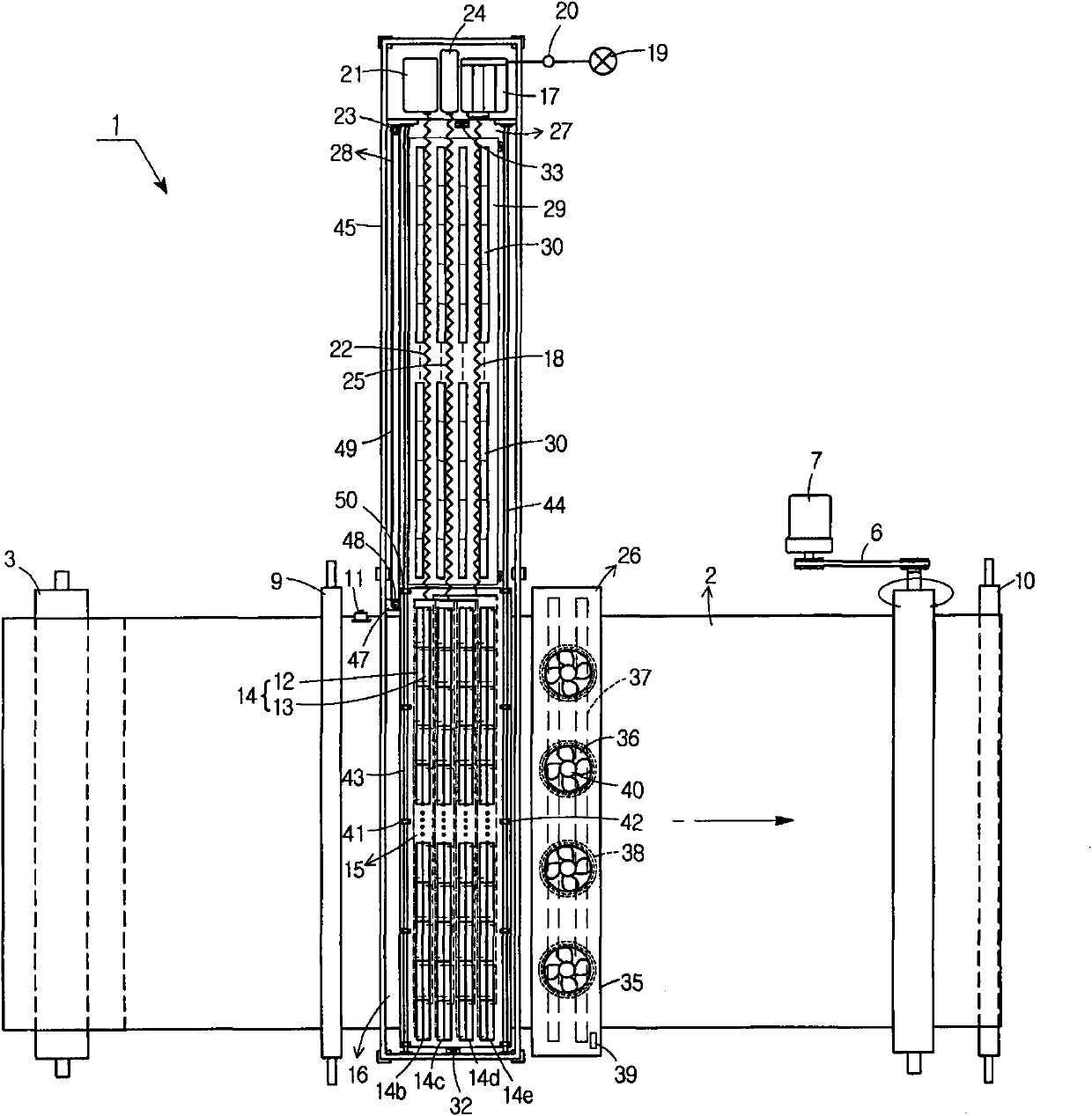
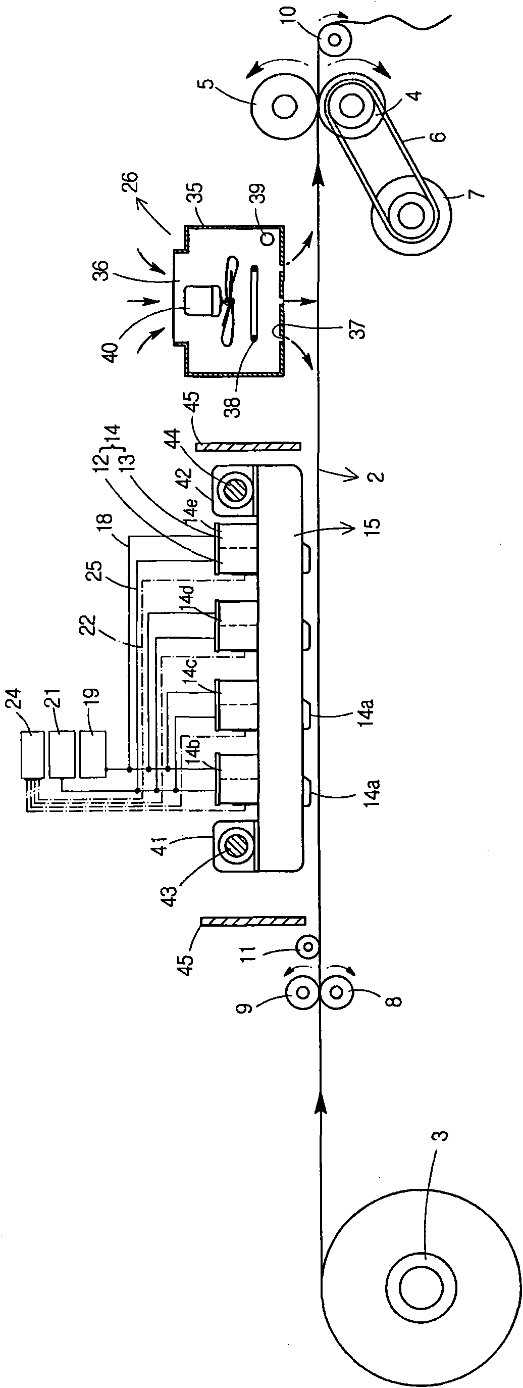
[0049] The digital dyeing high-speed output device 1 of the present invention includes: a supply drum 3 wound with a dyed object 2 of a certain width; a pair of upper and lower driving drums 4 for drawing out the dyed object 2 on the supply drum 3 and making it move forward; Passive drum 5; Power transmission device 6 and servo motor 7 for rotating the active drum 4 at a constant speed (or at a speed controlled b...


PUM


Abstract

The invention relates to digital textile printing high-speed output equipment using piezo jet technology, in particular to the digital textile printing high-speed output equipment of a large pattern. A dye bucket of the equipment is fixed, dyed matters such as a cloth material and the like move at a high speed; high-speed continuous textile printing operation is formed according to unit width or required width; therefore, production efficiency can be greatly improved, the dye bucket which produces heat during the high-speed textile printing operation is forcibly cooled, and continuous high-speed textile printing can be guaranteed.

Description

technical field [0001] The invention relates to a high-speed output device for digital dyeing by utilizing piezoelectric ink-jet technology (piezo jet). The specific description is that the dye barrel of the device is fixed, and the dyed objects such as fabrics move at high speed to form high-speed dyeing with unit width or required width. The continuous dyeing operation can greatly improve the production efficiency. At the same time, the dye barrels that generate heat during the high-speed dyeing operation are forcedly cooled to ensure that the high-speed dyeing can continue. Background technique [0002] Generally speaking, the actual pattern output process is to prepare the image to be printed by using the computer and related software, that is, using image editing software such as Corel DRAW, Photoshop and Illustrator, and then use the RIP (Raster Image Processing) program to generate computer image data, and finally Output to a large pattern output device. [0003] The...

Claims


Application Information

Patent Timeline
Patent Type & Authority Patents(China)
IPC IPC(8): B41J2/17B41J3/407
Inventor 朴名焕
Owner 朴名焕
Why Eureka
Try Eureka