Signal reception circuit and isolated signal transmission device

a signal transmission and signal reception technology, applied in the direction of oscillator generators, pulse techniques, electronic switching, etc., can solve the problem of increasing circuit size, and achieve the effect of high speed

Active Publication Date: 2015-10-15
PANASONIC INTELLECTUAL PROPERTY MANAGEMENT CO LTD
View PDF2 Cites 7 Cited by
  • Summary
  • Abstract
  • Description
  • Claims
  • Application Information

AI Technical Summary

Benefits of technology

[0011]According to a signal reception circuit and an isolated signal transmission device in accordance with an aspect of the present disclosure, a signal can be output at high speed.

Problems solved by technology

The isolated power source, however, leads to increased circuit size.

Method used


Image

  • Signal reception circuit and isolated signal transmission device
  • Signal reception circuit and isolated signal transmission device
  • Signal reception circuit and isolated signal transmission device

Examples


embodiments

[0041]Hereinafter, embodiments of the present disclosure will be described in detail using the drawings. Note that the embodiments described hereinafter all illustrate specific examples of the present disclosure. Features such as numerical values, shapes, materials, structural components, layout positions and connection states of structural components, steps, and the ordering of steps indicated in the following exemplary embodiments are merely examples, and are not intended to limit the present disclosure. The present disclosure is specified by the claims. Thus, among the structural components in the following exemplary embodiments, structural components that are not described in the independent claim indicating the broadest concept of the present disclosure are described as arbitrary or optional structural components.

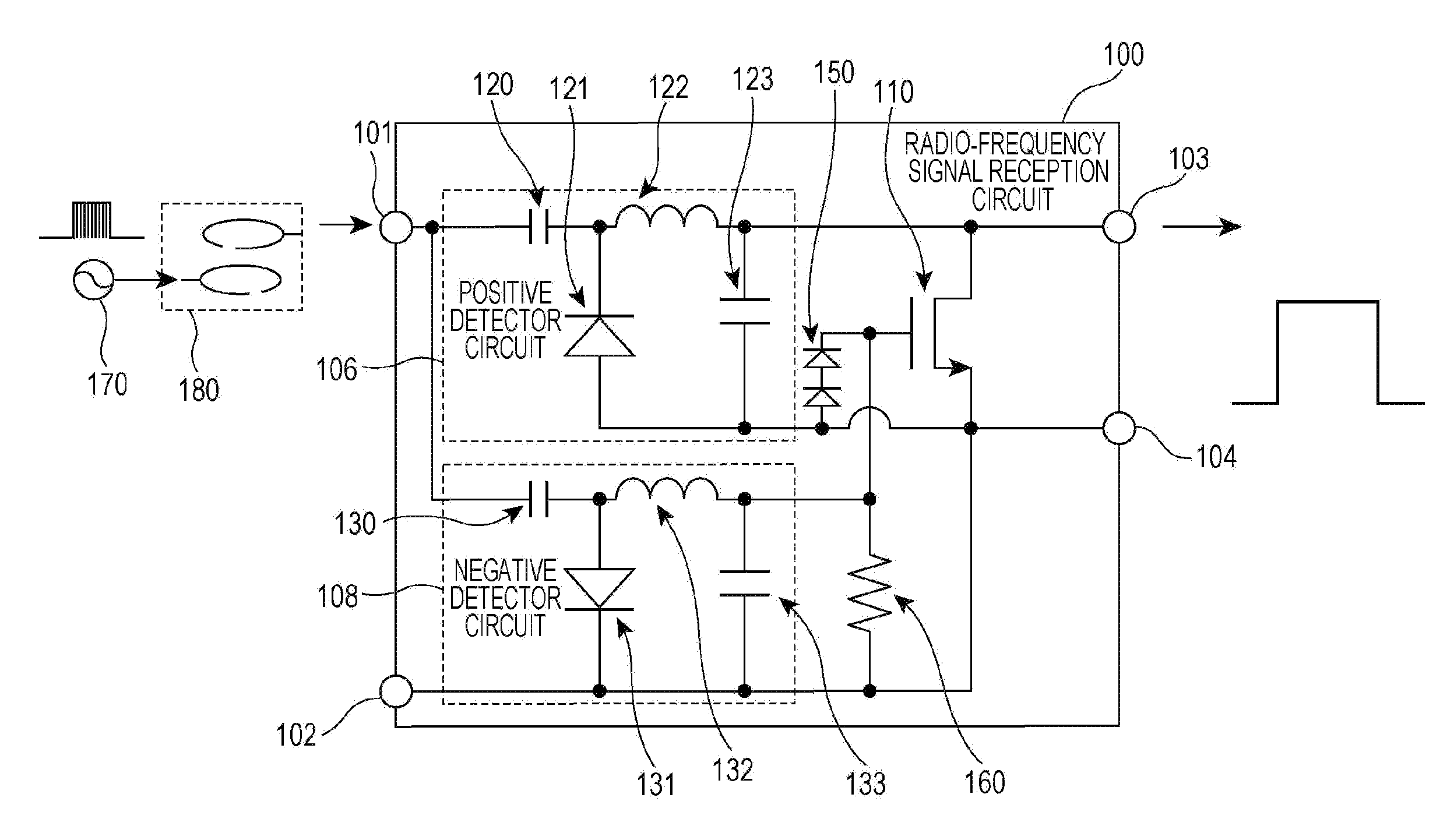
[0042]FIG. 1 is a circuit diagram illustrating an example of a radio-frequency signal reception circuit 100 according to the embodiment. The radio-frequency signal rec...


PUM


Abstract

A signal reception circuit according to an aspect of the present disclosure includes: an input terminal; an input reference terminal; an output terminal; an output reference terminal; a normally-on type transistor that includes a first terminal connected to the output terminal, a second terminal connected to the output reference terminal, and a control terminal; a first detector circuit that detects an input signal applied between the input terminal and the input reference terminal, to apply an output signal between the output terminal and the output reference terminal; and a second detector circuit that detects the input signal, to apply a negative voltage pulse to the control terminal of the transistor with the output reference terminal as a reference.

Description

BACKGROUND[0001]1. Technical Field[0002]The present disclosure relates to a signal reception circuit and an isolated signal transmission device. These are, for example, applied to a gate driver circuit that drives a gate terminal of a semiconductor switch.[0003]2. Description of the Related Art[0004]A gate driver circuit is a circuit that drives a semiconductor switch. The gate driver circuit controls the semiconductor switch on and off by applying a gate voltage to the gate terminal thereof. One high-voltage semiconductor switch is, for example, the insulated gate bipolar transistor (IGBT), which is a type of power semiconductor device. A typical gate driver circuit has a P-type transistor and an N-type transistor at the output part thereof. The semiconductor switch is turned on when P-type transistor operates, and is turned off when the N-type transistor operates. When the semiconductor switch is turned off, the gate current is withdrawn from the semiconductor switch.[0005]A gate ...

Claims


Application Information

Patent Timeline
Patent Type & Authority Applications(United States)
IPC IPC(8): H03K17/687
CPCH03K17/687H03K2017/6875H04B1/04H02J50/12H02J50/20H02J50/10
Inventor NAGAI, SHUICHI
Owner PANASONIC INTELLECTUAL PROPERTY MANAGEMENT CO LTD
Why Eureka
Try Eureka