

Method for operating a hybrid drive
A drive and operating mode technology, applied in the layout of multiple different prime movers of hybrid vehicles, general power plants, motor vehicles, etc., can solve problems such as inability to perform zero calibration, and achieve improved calculation/matching effects
- Summary
- Abstract
- Description
- Claims
- Application Information
AI Technical Summary
Problems solved by technology
Method used
Image

Examples
Embodiment Construction
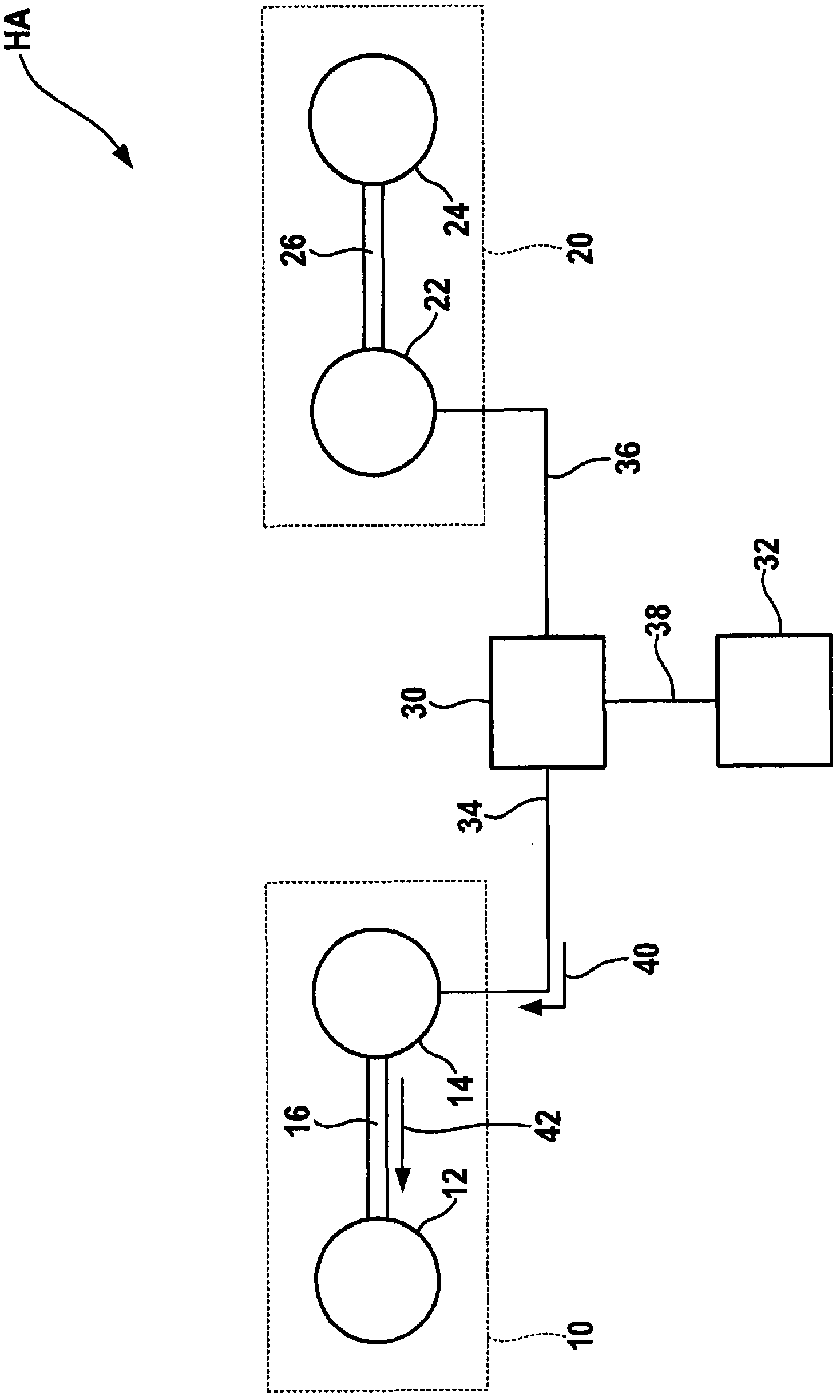
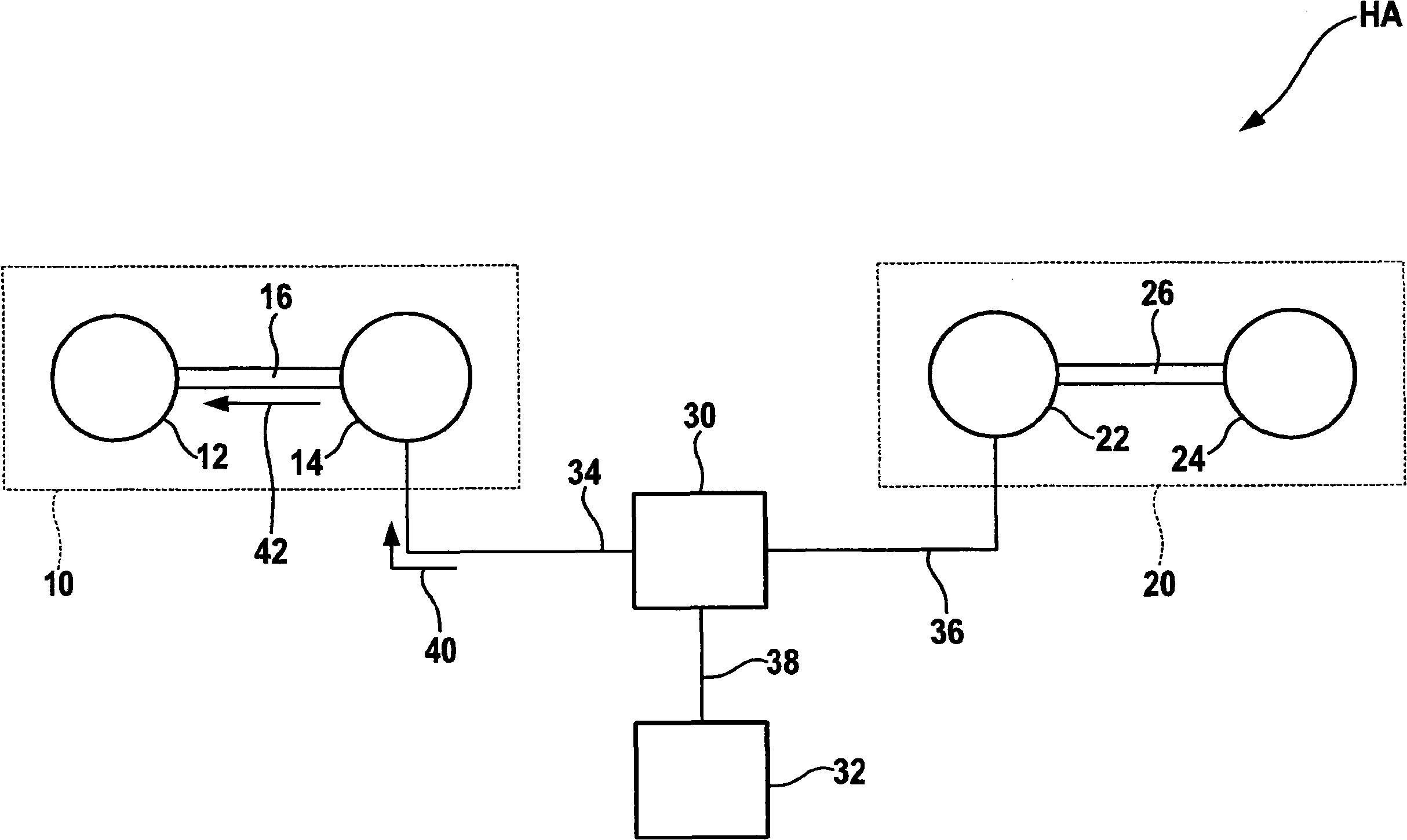
[0016] figure 1 The hybrid drive HA of the series basically includes a supply unit 10 and a drive unit 20 . The supply unit 10 consists of an internal combustion engine 12 and a generator 14 . Internal combustion engine 12 and generator 14 are coupled via a power transmission connection 16 . The drive unit 20 is composed of an electric motor 22 and a drive train 24 . The electric motor 22 and the drive train 24 are coupled via a force-transfer connection 26 .
[0017] Energy transfer unit 30 is connected to generator 14 , electric motor 22 and battery 32 by means of lines 34 , 36 and 38 . The generator 14 , the electric motor 22 and the battery 32 can be operated as energy sources or as energy reducers.
[0018] The supply unit 10 serves the purpose of supplying electrical energy to a vehicle unit, for example a drive unit 20 . For this purpose, the generator 14 is driven by the internal combustion engine 12 . The generator 14 converts the mechanical energy emitted by th...
PUM
 Abstract
Description
Claims
Application Information