Air foam slug flow driving process for oil recovery of oil field

An air-foaming and oil-displacing technology, which is applied in the fields of fluid production, earth-moving drilling, wellbore/well components, etc., can solve the problems of poor water injection effect, low oil displacement efficiency, and difficult water injection capacity, etc., so as to improve the sweep efficiency and improve the Oil displacement efficiency, effect of reducing sewage volume and water treatment intensity

Inactive Publication Date: 2011-05-18
YANCHANG OIL FIELD
3 Cites 24 Cited by

AI-Extracted Technical Summary

Problems solved by technology

[0013] The technical problem to be solved by the present invention is to provide an air foam slug flooding process for oil field oil recovery, which is reasonable in design, simple in construction steps, convenient in implementation and good in use effect, and can effectively...

Method used

Experimental result shows, after carrying out air foam flooding, its oil displacement efficiency is improved to 74.34%~88.02% from 50%-58.14% of water flooding, and oil displacement efficiency improves about 30 percentage points on average (see indoor rock core for details the experimental results).
[0068] Alternate injection of small slugs of air and foam liquid has the highest oil displacement efficiency and is easy to inject. Judging from the qualit...

Abstract

The invention discloses an air foam slug flow driving process for the oil recovery of an oil field, comprising the following steps of: 1 determining type and proportion of the used foam liquid, slug volume ratio and on-site injection manner of the used air and the foam liquid during the air foam slug flow driving by an indoor test; and 2 carrying out the air foam liquid slug flow driving on site,wherein the oil flow driving process comprises the following steps of: preparation before the oil flow driving; slugging a pad fluid; slugging the air foam; alternatively injecting the air and foam liquid slug from a specially manufactured device to a target well for many times; and continuously carrying out the oil flow driving on the target well by a water or air injection method according to the dynamic change condition of the target well and a conventional oil displacement method after the injection of the air foam slug is finished. The invention has the advantages of reasonable design, simple and convenient construction steps, good use effect and convenience of realizing, can effectively solve various practical problems of poor water injection effect, difficult improvement on the water injection capability, poor oil flow driving efficiency and the like during the ultralow reservoir waterflooding.

Application Domain

Technology Topic

Injection airOil displacement +1

Image

  • Air foam slug flow driving process for oil recovery of oil field
  • Air foam slug flow driving process for oil recovery of oil field

Examples

  • Experimental program(1)

Example Embodiment

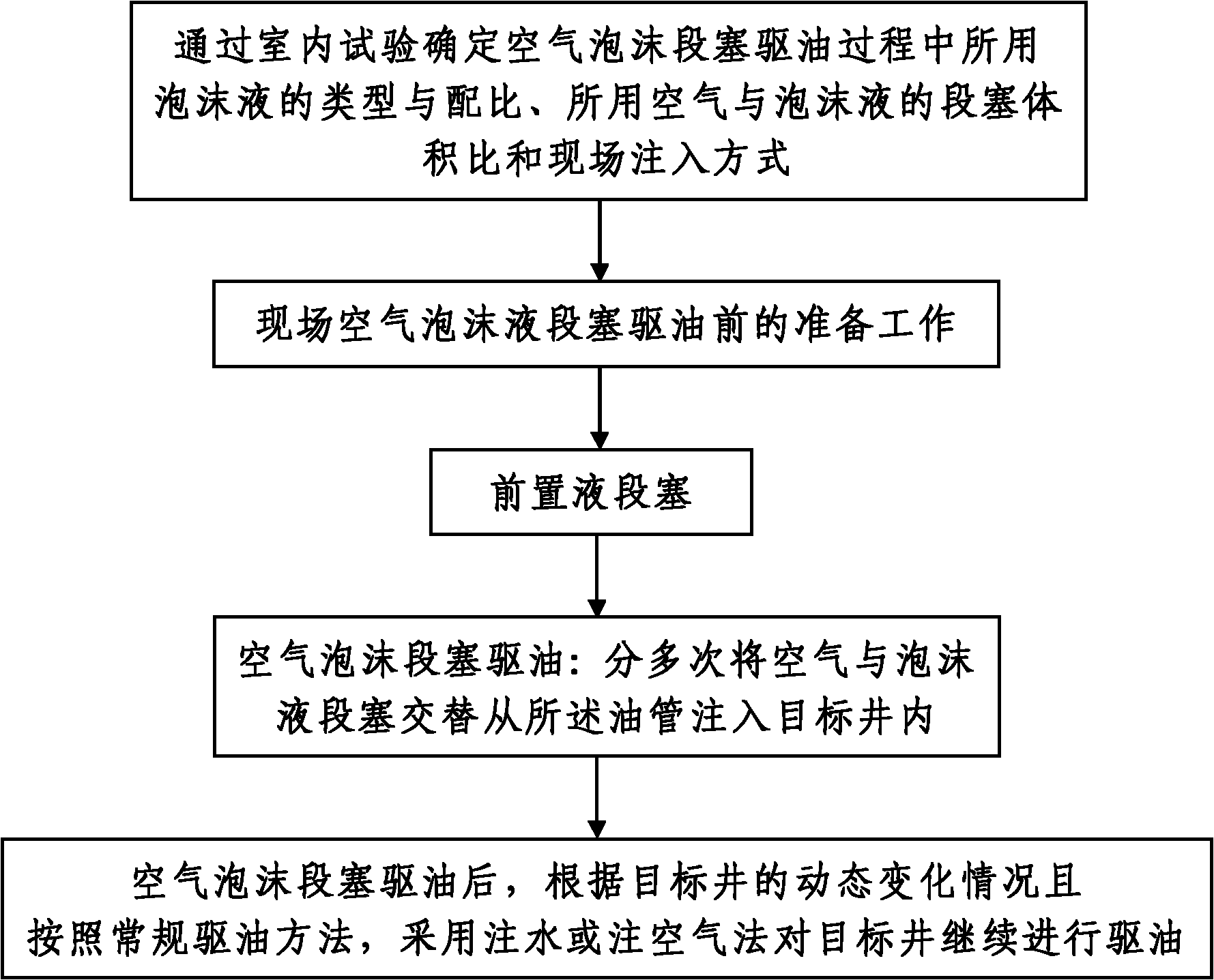
[0049] like figure 1 Shown a kind of air foam slug flooding technology for oil field oil recovery, comprises the following steps:
[0050] Step 1. Determine the type and proportion of foam liquid used in the process of air foam slug flooding, the slug volume ratio of air to foam liquid used in the process of air foam slug flooding, and the field injection method through laboratory tests. The indoor test The determination process is as follows:
[0051] 101. Determine the type and proportion of foam liquid used in air foam slug flooding, and the determination process includes the following steps:
[0052] 1011. According to the conventional foam flooding method, judge and collect various surfactants suitable for foam flooding of the target well.
[0053] 1012. Perform a foaming test on the various surfactants collected in step 1011 according to the conventional foaming test method, so as to test the foaming ability of each surfactant, that is, the foaming height, and record the test results; At the same time, in the foaming test process, add a foam stabilizer to the tested surfactant and carry out a foam stabilizing test on various surfactants according to the conventional foam stabilizing test method, so as to determine the foam stability of each surfactant, that is, the foam The half-life is tested and the test results are recorded; after the foaming test and the foam stabilization test, the recorded test results are compared and analyzed, and two or more foaming abilities are initially screened out of the various surfactants tested. Relatively strong surfactant with relatively good foam stability.
[0054] 1013. Under a plurality of different mass concentration conditions in the range of 0.1% to 1.0% mass concentration, respectively conduct a foaming test and a foam stabilizing test on the two or more surfactants selected in step 1012, and obtain a result from the test The foaming ability and foam stability data of each surfactant in different mass concentrations are recorded; at the same time, after adding a variety of foam stabilizers to each surfactant, the foam stabilization test is carried out, and the addition of different foam stabilizers Record the foam stability data of each surfactant under different conditions; after the test, compare and analyze the recorded test data, and screen out the foaming ability at different mass concentrations from the two or more surfactants tested. and various surfactants with relatively good foam stability and relatively low price; in this step, the mass concentration is the mass percentage of the surfactant in the prepared foam liquid.
[0055] 1014. According to the conventional oil-water interfacial tension test method, carry out the oil-water interfacial tension experiment on the various surfactants screened out in step 1013, and record the tension data of the oil-water interface after adding each surfactant; The recorded oil-water interfacial tension data is compared and analyzed, and a surfactant with the lowest oil-water interfacial tension is screened out among the various surfactants tested. At this time, the surfactant screened out is prepared in step 1. Foaming agent used in foaming liquid.
[0056] 1015, compare and analyze the foam stability data of each surfactant recorded in step 1013 under the condition of adding different foam stabilizers, and select a foam stabilizer with the best foam stability as the selected foam stabilizer in step 1014 The foam stabilizer of tensio-active agent; Combining in step 1013 to the foaming ability and the foam stability test data of the tensio-active agent screened out in step 1014 at different mass concentrations, determine the surfactant pair screened out in step 1014 The mass concentration of the surfactant and the mass concentration of the added foam stabilizer, the mass concentration of the surfactant is 0.1% to 1.0%, and the mass concentration of the added foam stabilizer is 0.01% to 0.1%.
[0057] To sum up, step 101 is actually a comprehensive indoor evaluation of the foam liquid formula, and the indoor evaluation of the foam liquid formula is mainly the foaming ability of the foaming agent, the ability of the foam system to form ultra-low interfacial tension with crude oil, and the foam system Evaluate the ability to enhance oil recovery.
[0058] Among them, the evaluation of foam liquid system performance is generally characterized by foaming ability (ie, foaming height) and foam stability (ie, foam half-life). In this embodiment, the various surfactants collected in step 1011 are 28 commonly used surfactants such as AOS, ABS, and AES. During the actual oil displacement process, the type and quantity of the surfactant collected in step 1011 can also be adjusted accordingly according to actual needs. In step 1012, the foaming test and foam stabilizing test of ground injection water were carried out through the foaming and foam stabilizing properties of 28 different surfactants such as AOS, ABS, AES, and 27 kinds of surfactants such as AOS, ABS, AES, etc. Foaming test and foam stabilizing test of different surfactants were carried out to simulate the foaming test and foam stabilizing test of formation water, so as to carry out primary selection to the various surfactants collected. When actually performing primary selection, in step 1012 The number of selected two or more surfactants is five or six. In this example, through preliminary selection, it was found that five foaming agents, such as KDQP-2, BK-5, BK-6, BK-7 and BK-8, had a large amount of foam at a concentration of 0.5%, all greater than 420ml, and the half-life It is relatively long and more than 180min. At the same time, it has good compatibility with ground injection water and simulated formation water, and does not produce precipitation. For the five kinds of surfactants with good foaming and foam stabilizing properties screened above, in order to understand their foaming and foam stabilizing properties in formation water at a low concentration of 0.1%, further screening experiments were carried out. It was found that the foaming agent with better foam performance at higher concentration also had better foaming and foam stabilizing performance at lower concentration. Among them, BK-6 foaming agent has the largest foaming volume and the longest foam stabilization time. Therefore, in the present embodiment, the surfactants screened out in step 1013 are 5 kinds of foaming agents, and the 5 kinds of foaming agents are KDQP-2, BK-5, BK-6, BK-7 and BK-8 respectively Foaming agent, and determine the foaming amount of BK-6 foaming agent is the largest and the foam stabilization time is the longest among the five kinds of foaming agents.
[0059] In step 1014, through the tension experiment between the foam liquid system and the crude oil interface, the 5 kinds of foam liquid systems with good foamability and foam stability screened out in step 1013 have carried out the oil-water interfacial tension experiment, and the test results show that adding BK The oil-water interfacial tension after -6 foaming agent is the lowest, which is 0.14363mN/m, which is only 0.636% of the interfacial tension between formation water and crude oil. Therefore, in this embodiment, the surfactant screened out in step 1014 is BK-6 foaming agent.
[0060]In step 1015, through the comprehensive optimization research on the foaming and foam stabilization experiments of the foam liquid system and the experimental results of the interfacial tension experiment between the foam liquid system and crude oil, it is finally determined to adopt the formula of 0.5% BK-6+0.05% BK-51 Complex foam fluid. That is to say, the foam stabilizer selected in step 1015 is the BK-51 foam stabilizer, and the mass concentration of the BK-6 foam stabilizer is 0.5%, and the mass concentration of the added foam stabilizer is 0.05%.
[0061] 102. Determine the slug volume ratio of air to foam liquid used in the air foam slug flooding process and the on-site injection method. The determination process is as follows:
[0062] 1021. Water flooding simulation test: According to the conventional water flooding simulation experiment method, the ground injection water used in the field oil displacement process is used to conduct water flooding simulation experiments on the tested rock cores respectively, and after the water flooding simulation experiment Record oil output data.
[0063] 1022. Using the alternate air and foam liquid slug flooding method, and under the conditions of multiple different gas-liquid ratios in the range of the volume ratio between air and foam liquid, that is, the gas-liquid ratio, within the range of 1:1 to 5:1, the In step 2021, after the water flooding simulation experiment, the multiple tested cores were subjected to the air foam liquid slug flooding simulation experiment respectively, and the oil displacement of each tested core under different gas-liquid ratio conditions obtained from the test After the air-foam liquid slug flooding simulation experiment is over, compare the data on the amount of oil driven out of each tested core under different gas-liquid ratios, and select the oil driven out from multiple gas-liquid ratios accordingly. A gas-liquid ratio with a relatively large amount and a relatively low price is used as the slug volume ratio for on-site air-foam liquid slug flooding. The slug volume ratio determined in this step is N:1, where N=1-5.
[0064] At the same time, it is determined that the on-site injection method of air-foam liquid slug flooding is the injection method of alternately injecting air and foam liquid and performing underground foaming; The volume ratio between the injected foam liquid and the injected air volume is the underground volume converted from the injected air.
[0065] In this embodiment, in step 102, the air foam flooding experiment after water flooding and the direct foam flooding experiment were carried out on 8 rock cores in the room respectively, and when performing air foam flooding after water flooding, the gas-liquid Alternate slug flooding of small slugs with air and foam liquid at a ratio of 1:1, foam liquid and air slug flooding with different gas-liquid ratios and displacement amounts, and large slugs with gas-liquid ratios of 6:1 and 3:1 Four displacement experiments of air foam flooding and air foam flooding with a gas-liquid ratio of 1:1. According to the experimental results, in the two experiments of alternating air and foam liquid flooding with a gas-liquid ratio of 1:1 in small slugs and air-foam flooding with a gas-liquid ratio of 1:1, the increase in oil displacement efficiency is comparable, both at 30%. , and the improvement range of other displacement methods is lower.
[0066] The final oil displacement efficiency is relatively high, ranging from 87.5% to 88.04%, which is slightly higher than the final efficiency of air foam flooding after water flooding. At the same time, it is also found in the experiment that the injection pressure is too high and the injection is difficult when the foam is injected directly. This problem can be solved by replacing it with a slug of air and foam liquid.
[0067] From the perspective of gas-liquid ratio, the final displacement efficiencies of gas-liquid ratio of 3:1 and 1:1 are basically the same.
[0068] Alternate injection of small slugs of air and foam fluid has the highest oil displacement efficiency and is easy to inject. Judging from the quality of the generated foam, the gas-liquid ratio is between 2:1 and 4:1, and the generated foam is very delicate, and it is easy to gas channel when the gas-liquid ratio is greater than 5:1. In the displacement experiment, the final oil displacement efficiency of the gas-liquid ratio of 1:1 and 3:1 is equivalent, but considering the economy, the recommended gas-liquid ratio is 3:1. In this embodiment, the slug volume ratio determined in step 1022 is 3:1.
[0069] The experimental results show that after air foam flooding, the oil displacement efficiency increases from 50%-58.14% of water flooding to 74.34%-88.02%, and the average oil displacement efficiency increases by about 30 percentage points (see the experimental results of indoor cores for details ).
[0070] In addition, before the air-foam liquid slug flooding is carried out on site, the safety of the air injection process needs to be demonstrated in combination with the actual situation on site. In the actual demonstration, the analysis is based on the theory of low-temperature oxidation kinetics. Crude oil oxidation is a process controlled by chemical reaction kinetics. A simple Arrhenius equation can be used to describe the change of reaction rate with oxygen partial pressure and temperature. That is, the oxygen in the air and the underground crude oil oxidation reaction rate have an exponential curve relationship with the formation temperature, and the higher the temperature, the faster the oxidation rate. Through the analysis and evaluation of domestic and foreign low-temperature oxidation indoor experiment results and domestic and foreign air injection, air foam field test low-temperature oxidation evaluation analysis and research, the low-temperature oxidation time prediction is made after comparing and analyzing the characteristics of the oil reservoir in the Tang 80 well area and the oil reservoir that has been injected with air , it is calculated that the time required to reach the safe oxygen content after low-temperature oxidation in the Tang 80 well area is about 90-100 days, which is basically consistent with the field test results. It shows that when the formation temperature is lower than 30°C, air injection can also cause low-temperature oxidation reaction. In a word, the safety of air injection is guaranteed by adopting safety precautions such as casing gas passing through the elevated blowdown pipe at the air injection site in the Tang 80 well area.
[0071] In addition, it is necessary to demonstrate the feasibility of the injection pressure of foam (air) flooding, design a reasonable on-site injection method, and carry out the experimental research on the displacement of the air injection pressure chamber. From the perspective of water permeability, the air permeability of the core is 2-4 times that of water, and air injection is easier than water injection; from indoor core flooding experiments, the pressure of simple gas injection is lower than that of water injection, but after foam formation, the injection pressure And the injection pressure changes regularly; the displacement pressure of alternating air-foam injection is lower than that of pure foam injection. Through the comparative study of gas injection-water injection pressure at home and abroad, it is found that the air suction capacity is 1.7-3.4 times the water absorption capacity, which is equivalent to the ratio of single-phase gas/water absolute permeability. Calculated by taking the average air absorption index as about 2 times the water absorption index, it is predicted that the air injection pressure of the air injection foam well group in the Tang 80 well area is: when the gas injection speed is 10m 3 /d (underground volume), the gas injection pressure is between 10-17MPa. Calculation shows that air can be effectively injected under 16MPa, and the injection of air and foam solution alternately can be carried out on-site injection construction in the way of underground foaming. In summary, through the demonstration of the gas injection pressure and the demonstration and research of the air injection speed, the parameters of the selected air compressor are the rated parameters: pressure 25MPa, displacement 3.5m 3 /min.
[0072] Step 2: Carry out air foam liquid slug flooding on site, and the oil flooding process is as follows:
[0073] 201. Preparatory work before oil displacement: build a foam liquid distribution room for preparing pre-injected foam liquid and an air distribution room for injecting air around the target well; The mass concentration of agent and foam stabilizer is used to prepare the foam solution in the foam solution room. At the same time, the air pre-injected into the target well is compressed into compressed air by using an air compressor and according to the conventional air injection method; The foam liquid injection pipeline drawn out and the air injection pipeline drawn from the gas distribution room are respectively connected with the oil pipe installed in the target well, and a driving pump is installed on the foam liquid injection pipeline and the air injection pipeline.
[0074] 202. Pre-fluid slug: start the driving pump installed on the foam liquid injection pipeline, and inject a volume of 100m into the target well through the tubing 3 ±5m 3 foam liquid. In this step, the injected foam liquid is also the foam liquid prepared in step 201,
[0075] 203. Air foam slug flooding: alternately inject air and foam liquid slugs from the tubing into the target well several times, each time for air injection is 24h±2h, and each time for foam liquid injection is N ×(24h±2h) and the gas injection pressure is 10MPa~17MPa, and the foam injection speed of single well is 10m 3 /d±1m 3 /d, the air injection speed of single well is 10m 3 /d±1m 3 /d and the volume of the injected air is the converted underground volume of the injected air; the ratio between the total volume of the injected air and the total volume of the foam liquid in this step is N:1. In actual operation, the time for each injection of air is 24h±2h, and the time for each injection of foam solution is 3×(24h±2h). During the actual oil displacement process, the injection time, injection pressure, injection speed, and injection volume of foam liquid and air can be adjusted accordingly according to actual needs. In this step, the injected foam liquid is also the foam liquid prepared in step 201 .
[0076] In this embodiment, the time for each injection of air in step 203 is 24 hours and the gas injection pressure is 16 MPa, the time for each injection of foam solution is 72 hours, and the speed of injecting foam solution in a single well is 10 m 3 /d, the air injection speed of single well is 10m 3 /d and the volume of injected air is the underground volume converted from the injected air.
[0077] 204. After the air foam slug is injected, according to the dynamic change of the target well and according to the conventional oil displacement method, continue to flood the target well by water injection or air injection.
[0078] In the present embodiment, the volume of prepared foam liquid in step 201 is 800m 3 , the volume of compressed air is 10.5×10 4 N m 3 And the converted underground volume is 2100m 3 , the volume of the injected foam liquid in step 202 is 100m 3 , the total volume of foam liquid injected into a single well in step 203 is 700m 3 , and the total volume of air injected into a single well in step 203 is 2100m 3.
[0079] The above are only preferred embodiments of the present invention, and do not limit the present invention in any way. All simple modifications, changes and equivalent structural changes made to the above embodiments according to the technical essence of the present invention still belong to the technical aspects of the present invention. within the scope of protection of the scheme.

PUM

PropertyMeasurementUnit
Volume800.0
tensileMPa
Particle sizePa
strength10

Description & Claims & Application Information

We can also present the details of the Description, Claims and Application information to help users get a comprehensive understanding of the technical details of the patent, such as background art, summary of invention, brief description of drawings, description of embodiments, and other original content. On the other hand, users can also determine the specific scope of protection of the technology through the list of claims; as well as understand the changes in the life cycle of the technology with the presentation of the patent timeline. Login to view more.

Similar technology patents

Independent background wall structure

InactiveCN107060241AFacilitate large-scale production and processingSimplify construction stepsCovering/liningsSpecial ornamental structuresWall plateEngineering
Owner:浙江友邦集成墙面有限公司

Classification and recommendation of technical efficacy words

  • Simplify construction steps
  • Easy construction

Hand-held machine tool

Owner:ROBERT BOSCH GMBH
Why Eureka
Try Eureka