
Pit pile anchor breast wall concrete breast beam structure and construction method thereof

A construction method and concrete technology, which is applied in the direction of foundation structure engineering, excavation, sheet pile walls, etc., can solve the problems of steel waist beams affecting construction safety, long construction time, high construction cost, etc., and achieve shortened construction time, simple construction method, The effect of simplifying the construction steps

Inactive Publication Date: 2008-10-08
BEIJING CONSTR ENG GRP CO LTD +1
View PDF0 Cites 18 Cited by
  • Summary
  • Abstract
  • Description
  • Claims
  • Application Information

AI Technical Summary

Problems solved by technology

[0003] The purpose of the present invention is to provide a concrete waist beam structure of foundation pit pile anchor retaining wall and its construction method, to solve the technical problem that removing the shaped steel waist beam will affect the construction safety and delay the construction period in the pile anchor retaining wall structure; and solve the traditional The construction time of foundation pit support structure in construction engineering is too long, too much material is wasted, the construction is complicated, and the construction cost is too high

Method used


Image

  • Pit pile anchor breast wall concrete breast beam structure and construction method thereof
  • Pit pile anchor breast wall concrete breast beam structure and construction method thereof
  • Pit pile anchor breast wall concrete breast beam structure and construction method thereof

Examples


Embodiment Construction

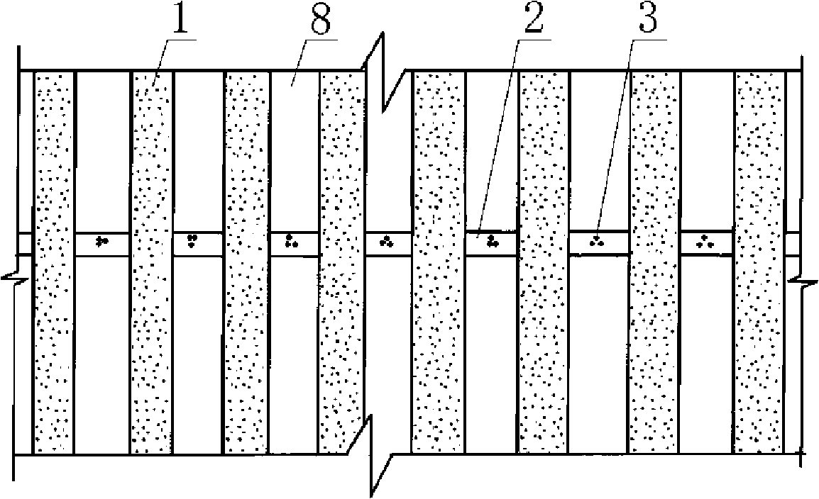
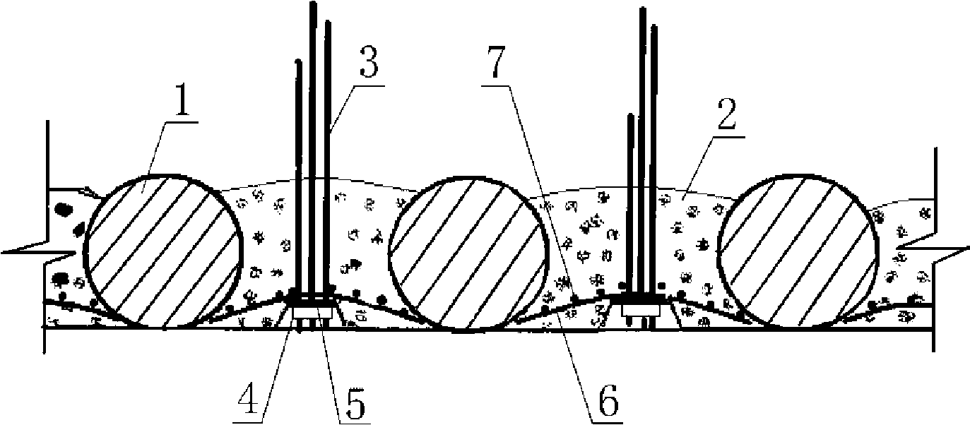
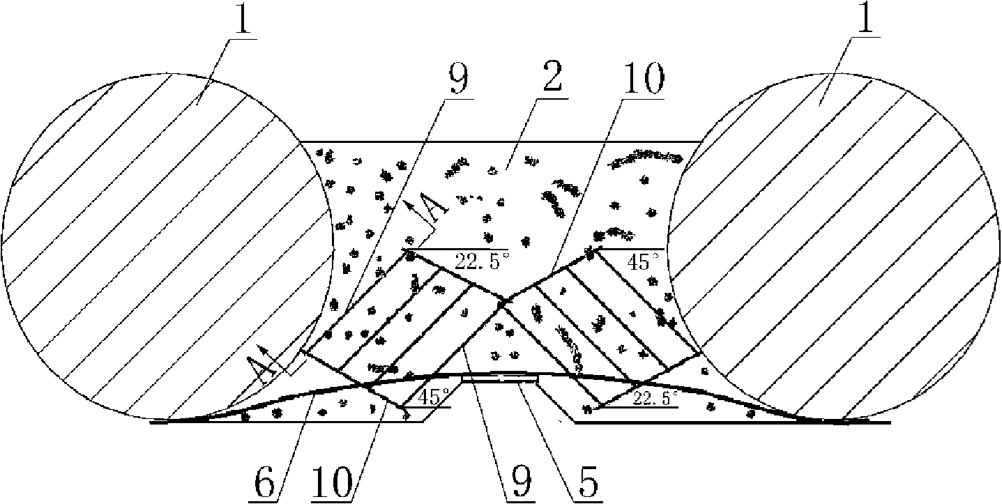
[0045] Examples see figure 1 , figure 2 As shown, this kind of foundation pit pile anchor protection wall concrete waist beam structure has a row of slope protection piles 1 arranged at intervals in the side wall of the foundation pit, and the prestressed anchors are fixed and fixed into the soil 8 between the piles of the slope protection piles. Bar 3, a lateral waist beam is also arranged on the side wall of the foundation pit. The above waist beam is a concrete waist beam 2. The concrete waist beam 2 is located between the piles of the concrete slope protection pile 1, and is connected to the prestressed anchor 3 by pouring. The outer side of the waist beam 2 is flush with the outer skin of the concrete slope protection pile 1, the inner side of the concrete waist beam is close to the inner end of the concrete slope protection pile, and the inner side of the concrete waist beam is distributed near the outer side. The sheet is wrapped on the outside of the pile body of the row...


PUM


Abstract

Disclosed is a concrete middle beam structure with foundation pit piles and anchor breast wall and the construction method thereof. Prestressed anchor rods are fixed between slope protection piles towards the soil between piles, and side wall of the foundation pits is also provided with transverse concrete middle beams which are between concrete slope protection piles and are in casting connection with the prestressed anchor rods; the outer lateral surface of the transverse concrete middle beams is as parallel and level as the sheath of the pile bodies of the concrete slope protection piles; the inner lateral surface is close to the inner end of the pile bodies of the concrete slope protection piles, and the inner part close to the outer lateral surface is distributed with reinforced nets which are coated at the outer lateral surface of the pile bodies of the row of the concrete slope protection piles and connected with anchor plates of the prestressed anchor rods; the prestressed anchor rods are embedded into the soil between piles from the side wall of the foundation pits, wherein, the anchor heads are positioned in the inner side of the connecting surface at the outer lateral surface of the row of the concrete slope protection piles. The structure of the invention changes the middle beams of section steel and the state that the prestressed anchor heads extrude the pile bodies, can reduce the excavation volume of foundation pits and needs no hoisting equipment to lift section steel middle beam, thereby greatly shortening construction time, simplifying construction steps and reducing construction cost.

Description

Technical field [0001] The invention relates to a construction engineering foundation pit supporting structure and a construction method thereof. Background technique [0002] In foundation engineering, traditional deep foundation pit support often adopts pile-anchor wall protection structure. Several pre-stressed anchor rods are used in the soil between the slope protection piles, and the pre-stressed anchor rods are connected to the slope protection piles through horizontal steel waist beams. Anchor together. The disadvantage is that when the engineering building uses the pile as the outer edge of the structure, the profile steel waist beam and the prestressed anchor head that protrude the pile must be removed. At this time, if the completed structure has not yet formed the top unloading of the slope protection pile, the rash removal of the steel waist beam will affect the construction safety. In order to prevent the occurrence of engineering accidents, the construction period ...

Claims


Application Information

Patent Timeline
Patent Type & Authority Applications(China)
IPC IPC(8): E02D5/76E02D5/20E02D17/04
Inventor 胡裕新汪亚冬刘爱玲于大海王华萍
Owner BEIJING CONSTR ENG GRP CO LTD
Learn More