Composite oil-gas separation device
- Summary
- Abstract
- Description
- Claims
- Application Information
AI Technical Summary
Problems solved by technology
Method used
Image

Examples
Embodiment Construction
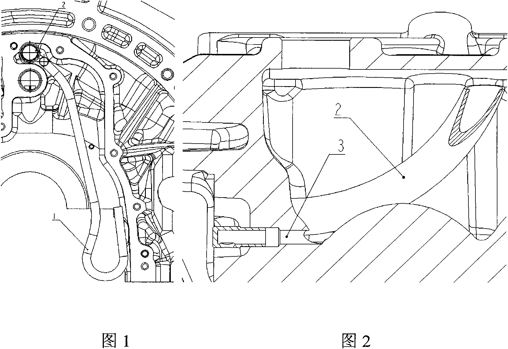
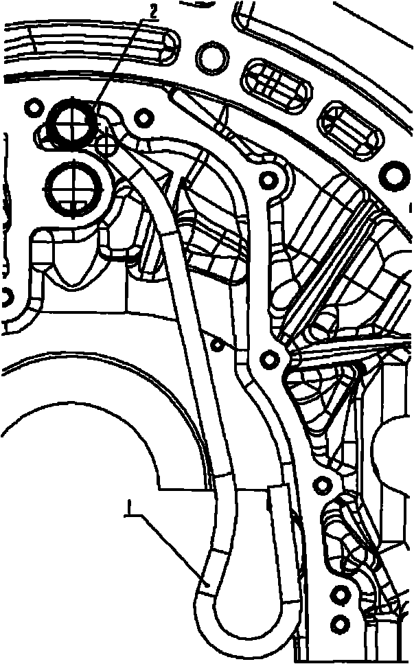
[0009] Below in conjunction with accompanying drawing, the present invention will be further described: as figure 1 As shown in -3, a compound oil-gas separation device is characterized in that: the gas guide pipe 1 and the oil return pipe 2 are connected at the air inlet of the oil-gas separation chamber at the rear end of the V-shaped engine, and the oil return pipe 2 is a "J"-shaped pipe It communicates with the oil pan; the oil return pipe inlet 3 is arranged at the bottom of the oil-gas separation chamber.
[0010] When the engine is running at high speed and heavy load, the oil-air mixture entering the oil-gas separation chamber enters the oil-gas separation chamber through the gas guide pipe 1, and the gas guide pipe 1 changes the direction of gas flow, so that the gas collides with the wall of the oil-gas separation chamber, thereby reducing the The flow rate of the oil-air mixture increases the separation capacity of the oil-gas separation chamber; at the same time, t...
PUM
 Abstract
Description
Claims
Application Information