Pneumatic power device

A power device and pneumatic technology, which is applied in the direction of fluid pressure actuators, servo motors, mechanical equipment, etc., can solve the problems of many valve precision patents, difficult and low-cost civilian use, and high market price, so as to reduce the volume and weight of the system, The effect of low carbon emissions and low quality requirements

Inactive Publication Date: 2011-05-18
朱米君
View PDF4 Cites 9 Cited by
  • Summary
  • Abstract
  • Description
  • Claims
  • Application Information

AI Technical Summary

Problems solved by technology

This not only causes a waste of energy, but also must be equipped with overflow and overpressure valves. These valves have high precision and many patents. With the increase of working pressure and flow rate, the market price is expensive. The value of valve sets ranges from thousands or even tens of thousands, making it difficult for current hydraulic power devices (such as hydraulic stations) to be used by low-cost civilians

Method used


Image

  • Pneumatic power device
  • Pneumatic power device
  • Pneumatic power device

Examples


Embodiment Construction

[0027] The present invention will be further described below in conjunction with accompanying drawing and embodiment of description, but protection scope of the present invention is not limited thereto:

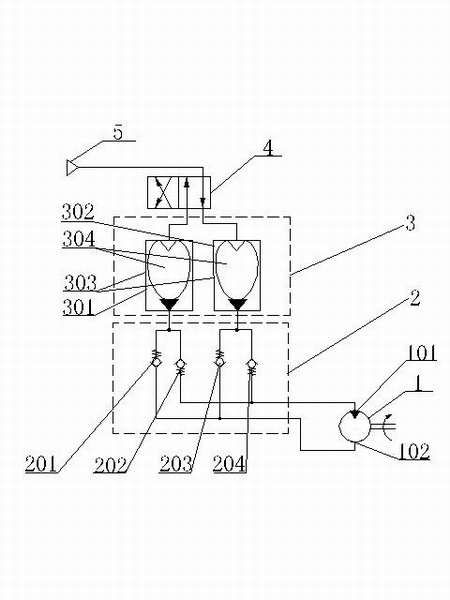
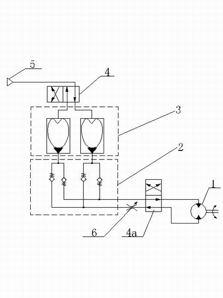
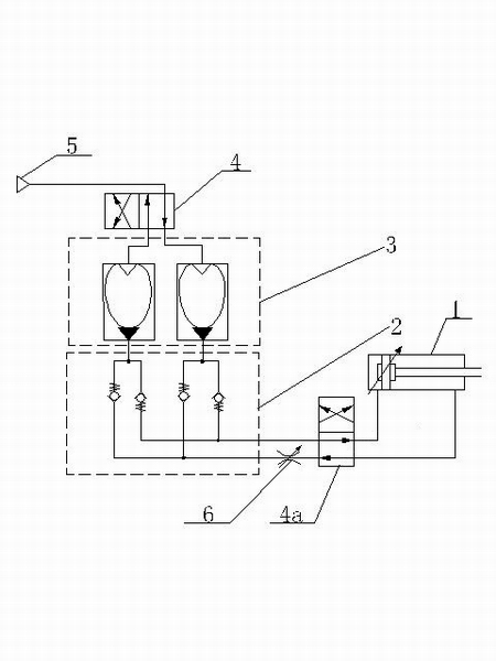
[0028] like Figure 1-4 As shown, a pneumatic power device includes an actuator 1, a bridge rectifier valve 2, a gas-liquid conversion multiplexer 3, a two-position four-way reversing valve 4, and an air source 5 that are sequentially connected back and forth. The rectifier valve 2 includes a first one-way valve 201, a second one-way valve 202, a third one-way valve 203 and a fourth one-way valve 204 that constitute a rectification backflow, and the gas-liquid conversion multiplexer 3 includes the first gas-liquid A liquid converter 301 and a second gas-liquid converter 302. One end of the first gas-liquid converter 301 is connected to the two-position four-way reversing valve 4, and the other end is connected to the first one-way valve 201 and the second one-way valve respec...


PUM


Abstract

The invention discloses a pneumatic power device, which belongs to the technical field of power conversion. The pneumatic power device comprises an executive device, a bridge rectifying valve, a gas-liquid conversion multiplexer, a two position four way reversal valve and a gas source which are sequentially connected, wherein the bridge rectifying valve comprises a first one-way valve, a second one-way valve, a third one-way valve and a fourth one-way valve which form a rectifying loop; the gas-liquid conversion multiplexer comprises a first gas-liquid converter and a second gas-liquid converter; one end of the first gas-liquid converter is connected with the two position four way reversal valve, and the other end of the first gas-liquid converter is connected with the first and second one-way valves respectively; and one end of the second gas-liquid converter is connected with the two position four way reversal valve, and the other end of the second gas-liquid converter is connected with the third and fourth reversal valves respectively. The pneumatic power device adopting a uniquely designed structure has a simple structure, a small volume, high working reliability and low cost,is simple and convenient to operate, and can be widely applied to the power provision of the vehicles such as bicycles, tricycles, automobiles and the like, machine tools, engineering machinery and the like.

Description

[0001] technical field [0002] The invention belongs to the technical field of power conversion, and in particular relates to an aerodynamic power device for converting gas energy into mechanical energy with simple structure, low cost and high efficiency. Background technique [0003] Traditional power devices currently used, such as internal combustion engines (also called heat engines), are power devices that convert chemical energy into mechanical energy, and work is done by consuming non-renewable energy such as gasoline and diesel. During the working process, it will emit toxic waste gas and emit working noise, which will seriously affect the air quality and pollute the environment. In the current situation of increasingly tight oil resources, the cost of use has become higher and higher. Moreover, the system structure is complex and bulky, which is contrary to the green energy advocated by the country. [0004] Currently used aerodynamic power devices, such as air m...

Claims


Application Information

Patent Timeline
Patent Type & Authority Applications(China)
IPC IPC(8): F15B11/072
Inventor 朱米君
Owner 朱米君
Why Eureka
Try Eureka