Automatic rubber-coating device installed on automatic coil winding machine

A technology of automatic winding machine and encapsulation device, applied in the direction of coil manufacturing, etc., can solve the problems of partial encapsulation, high quality requirements of enameled wires, large space occupation, etc., so as to improve the yield of encapsulation and ensure that the encapsulation does not pick up the wire. , The effect of reducing installation space

Active Publication Date: 2012-08-01
恩施州椿之藤生物科技有限公司
View PDF9 Cites 22 Cited by
  • Summary
  • Abstract
  • Description
  • Claims
  • Application Information

AI Technical Summary

Problems solved by technology

At present, common automatic lagging devices such as figure 1 The roller compression type shown is to use rollers to compress the coil skeleton for rubber wrapping, which is prone to defects such as not tight wrapping, not wrapping, and wrapping deviation.
In addition, the tape roll of this automatic gluing device is flat-packed, which not only takes up a lot of space, but also the tape needs to bypass multiple tape guide mechanisms, which will affect the viscosity of the tape; Higher requirements, that is, as the saying goes, "picking the line"

Method used


Image

  • Automatic rubber-coating device installed on automatic coil winding machine
  • Automatic rubber-coating device installed on automatic coil winding machine
  • Automatic rubber-coating device installed on automatic coil winding machine

Examples


Embodiment Construction

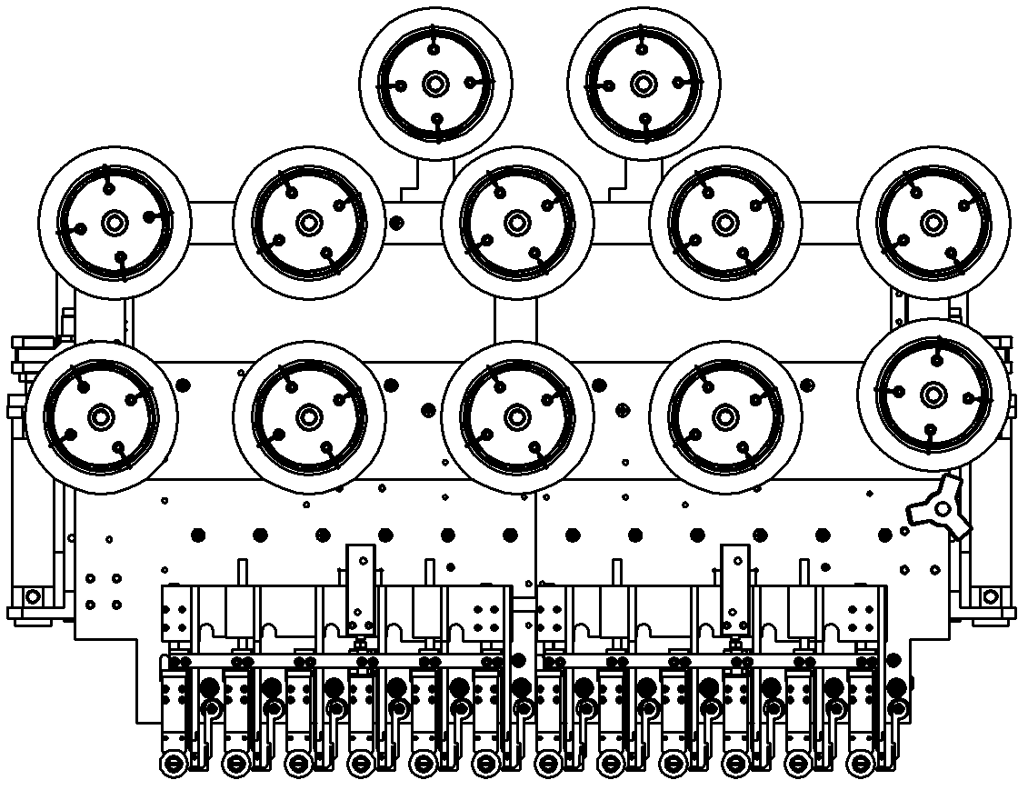
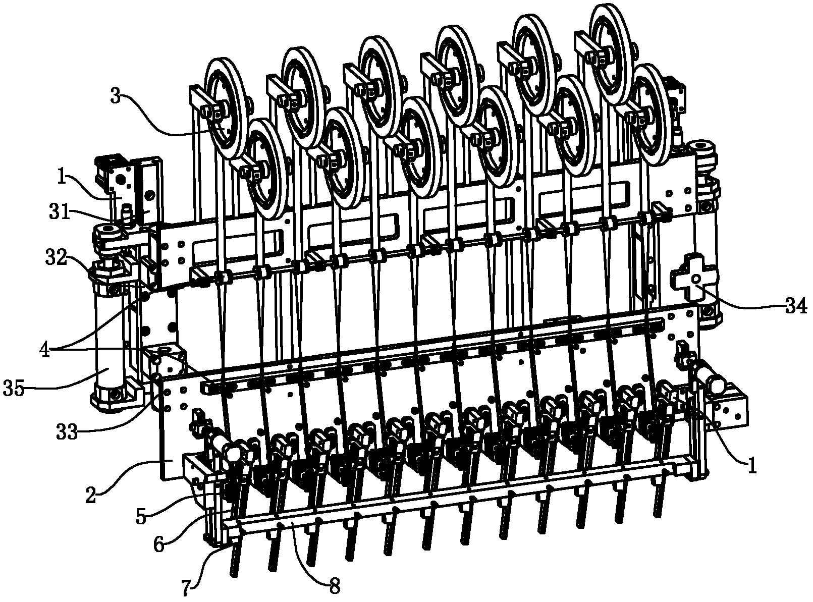
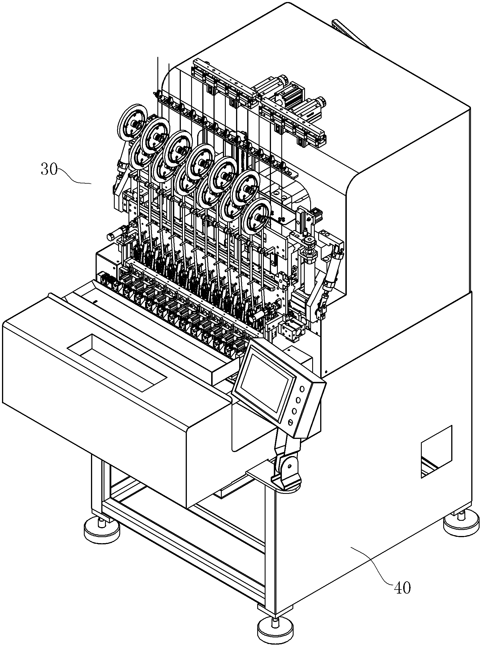
[0027] see figure 2 and image 3 , the automatic encapsulation device 30 of the present invention can be installed in image 3 The multi-axis automatic winding machine 40 shown is used to wrap the adhesive tape 10 on the winding rubber part 501 of the rubber covering part 50 (such as a coil bobbin) after winding, so that the rubber covering part 50 The windings are insulated, and the operation of the automatic rubber wrapping device 30 can be centrally controlled by the control unit (such as a programmable controller) of the automatic winding machine 40 . Such as figure 2 The automatic rubber wrapping device 30 includes a rubber wrapping base 1, a bottom plate 2, a tape unwinding wheel assembly 3, a tape guide assembly 4, a tape anti-deviation limit assembly 5, a tape winding assembly 6, a tape cutting assembly 7, a press Belt assembly 8, etc., wherein, tape unwinding wheel assembly 3, tape guide assembly 4, tape winding assembly 6, tape cutting assembly 7 and belt pressi...


PUM


Abstract

The invention discloses an automatic rubber-coating device installed on an automatic coil winding machine, which is used for coating a rubber belt on a rubber-coating piece. The automatic rubber-coating device comprises a movably-arranged base plate, a rubber belt unwinding wheel assembly, a rubber belt guide assembly, a rubber belt winding assembly, a belt cutting assembly and a belt pressing assembly, wherein the rubber belt unwinding wheel assembly, the rubber belt guide assembly, the rubber belt winding assembly, the belt cutting assembly and the belt pressing assembly are arranged on thebase plate. The rubber belt unwinding wheel assembly is positioned at the upper part of the base plate, the rubber belt guide assembly is positioned at the middle part of the base plate, and the rubber belt winding assembly, the belt cutting assembly and the belt pressing assembly are positioned at the lower part of the base plate. The rubber belt winding assembly comprises a winding elastic piece which is used for tightly pressing the rubber-coating device during rubber coating. The belt cutting assembly comprises an ending elastic piece, and a cutter used for cutting off the rubber belt is fixedly arranged on the ending elastic piece. The automatic rubber-coating device adopts the elastic piece to tightly press the rubber belt on the rubber-coating piece for coating rubber, and the traditional roller tightly-pressing rubber coating is replaced. The automatic rubber-coating device can greatly reduce the defects existing in the traditional rubber-coating device, as follows the coated rubber is loose, the rubber is not coated, the rubber is coated obliquely and the like. The ratio of fishing products of rubber coating is increased.

Description

technical field [0001] The invention relates to an automatic wrapping device on an integrated processing equipment for automatically wrapping a wound coil. Background technique [0002] Coils are commonly used components in the electronics industry. Insulating tape is an insulating material for winding transformers, motors, coils, etc. in the electronics industry. The automatic winding machine is used to wind the enameled wire on the bobbin to form a coil. In order to insulate the two windings connected in the coil, usually after winding a winding, it must first be covered by an automatic sealing device to form insulation. layer, and then the next winding can be wound. At present, common automatic lagging devices such as figure 1 The roller compression type shown is to use rollers to compress the coil frame for rubber wrapping, which is prone to defects such as not tight wrapping, not wrapping, and wrapping deviation. In addition, the tape roll of this automatic gluing d...

Claims


Application Information

Patent Timeline
Patent Type & Authority Applications(China)
IPC IPC(8): H01F41/12B65H81/00
Inventor 黄立波杨联军梁吉平
Owner 恩施州椿之藤生物科技有限公司
Why Eureka
Try Eureka