
Direct illumination type light guide plate of light-emitting diode (LED) backlight

A technology of LED backlight and light guide plate, which is applied in the direction of light guide, light source, point light source, etc. It can solve the problems of difficult backlight heat dissipation, inability to control light localization, and difficulty in thinning, etc., to achieve good heat dissipation, excellent uniform brightness non-bending effect

Inactive Publication Date: 2011-05-18
金芃 +1
View PDF0 Cites 9 Cited by
  • Summary
  • Abstract
  • Description
  • Claims
  • Application Information

AI Technical Summary

Problems solved by technology

The main disadvantages of edge-lit light-emitting elements of LED backlights are that they cannot perform local dimming, are difficult to apply to backlights of any size, and have poor heat dissipation.
The main disadvantages of direct-type light-emitting elements are that it is not easy to be thinner and more LED packages are used

Method used


Image

  • Direct illumination type light guide plate of light-emitting diode (LED) backlight
  • Direct illumination type light guide plate of light-emitting diode (LED) backlight
  • Direct illumination type light guide plate of light-emitting diode (LED) backlight

Examples


Embodiment Construction

[0025] Although the embodiments of the present invention will be described below, the following descriptions are only to illustrate the principles of the present invention, rather than limiting the present invention to the descriptions of the following embodiments.

[0026] Note: the following items are applicable to all embodiments of the direct-type light guide plate of the LED backlight of the present invention:

[0027] (1) The ratio of each part in each figure does not represent the actual ratio of each part in the embodiment.

[0028] (2) The LED backlight of the liquid crystal display is constituted by a light-emitting element composed of a single or multiple direct-type light guide plates.

[0029] (3) Other components of the light-emitting element of the LED backlight are not shown in FIG. 5 , and other components include light collecting sheets, polarizers, reflectors, frames, and the like.

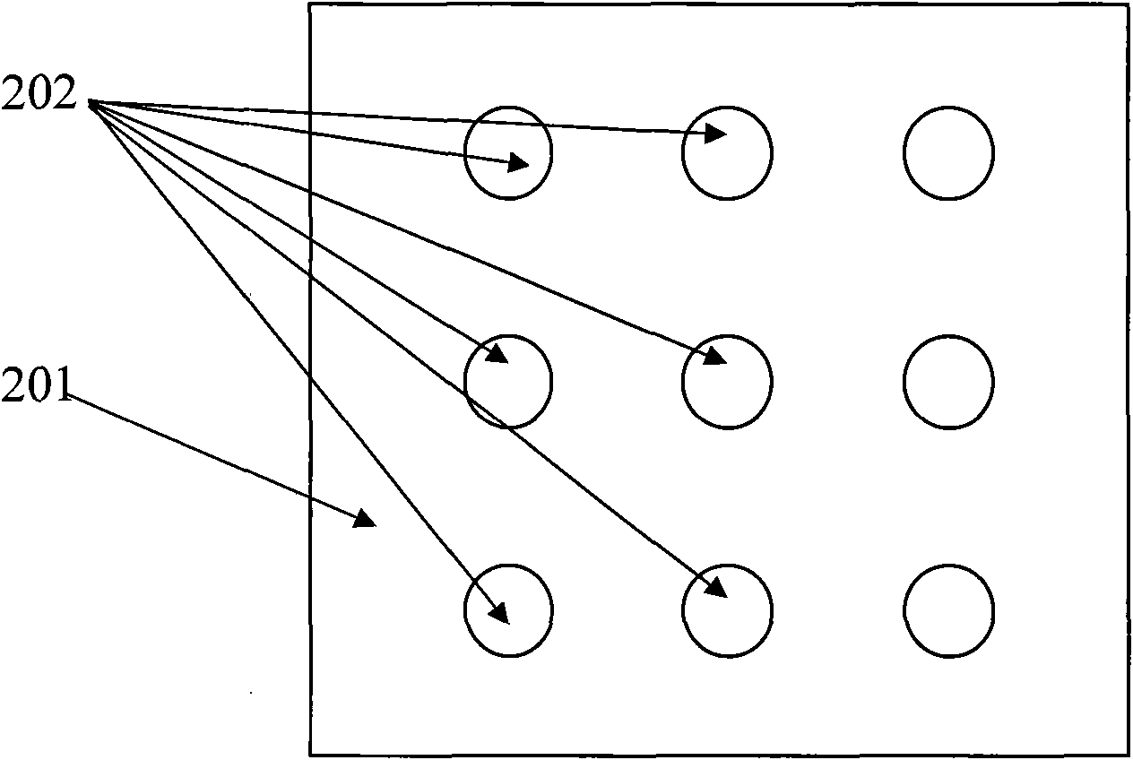
[0030] (4) A concave portion is formed on the top of the direct type light...


PUM


Abstract

The invention relates to a direct illumination type light guide plate of light-emitting diode (LED) backlight. The direct illumination type light guide plate of the LED backlight has double functions of diffusion and light guide and has the following essential characteristic that: a plurality of concave parts are formed on the top of the inner part of the direct illumination type light guide plate; and dots are formed at the bottom of the direct illumination type light guide plate. Light emitted by direct illumination type LED encapsulation passes through the bottom, enters the direct illumination type light guide plate and irradiates on the side faces of the concave parts; the side faces of the concave parts change the propagation direction of the light, so that the light is propagated in the direct illumination type light guide plate along the direction parallel to the light emitting surface of the direct illumination type light guide plate; and the dots reflects the light on the dots to the top of the direct illumination type light guide plate, therefore, the light guide plate is named as the direct illumination type light guide plate. The direct illumination type light guide plate is doped with light scattering particles, so the direct illumination type light guide plate has the scattering function at the same time. When a light emitting component of the direct illumination type light guide plate is adopted, the advantages of the direct illumination type light emitting component and a side light type light emitting component are achieved and the defects of the direct illumination type light emitting component and the side light type light emitting component are overcome.

Description

technical field [0001] The invention discloses a direct-type light guide plate of a direct-type light-emitting element of an LED backlight, which has the advantages of both the light guide plate of the side-light type light-emitting element of the LED backlight and the diffusion plate of the direct-type light-emitting element without their disadvantages, and belongs to Liquid crystal display technology field Background technique [0002] LEDs have been widely used in backlight devices for liquid crystal displays. There are mainly two commercial forms of LED backlights. One is the edge backlight light-emitting element of the LED backlight, and the other is the direct type (direct backlight) light-emitting element. The main disadvantages of the edge-lit light-emitting element of the LED backlight are that local dimming cannot be performed, it is difficult to apply to any size of the backlight, and the heat dissipation is poor. The main disadvantage of the direct-type light-e...

Claims


Application Information

Patent Timeline
IPC IPC(8): F21V8/00F21V7/10F21V13/00G02F1/13357F21Y101/02
Inventor 彭晖
Owner 金芃
Learn More