
Automobile body control system

A body control and control unit technology, applied in the field of automotive electronic control systems, can solve the problems of electronic module sampling port influence, interference system, functional disorder, etc., to improve anti-electromagnetic interference and stability, improve stability and reliability , to ensure the effect of normal use

Inactive Publication Date: 2011-05-18
CHERY AUTOMOBILE CO LTD
View PDF7 Cites 24 Cited by
  • Summary
  • Abstract
  • Description
  • Claims
  • Application Information

AI Technical Summary

Problems solved by technology

Although the cost of the control system is low, the currently used central control body control system generally has system failures caused by hardware interference and software defects.
For example, when the micro control unit fails, the relay output control unit will not be able to continue to drive the load to work
For another example, when the relay output control unit fails, the micro control unit cannot get feedback in time, thereby reducing the stability of the body control system
In addition, with the application of various control programs in the body control system, the stability of the body control system caused by the abnormal operation of the program has become increasingly prominent
[0006] Moreover, a large number of motors are currently used on vehicles, and there is relatively strong electromagnetic interference during the working process of the motors; electronic modules will also generate electromagnetic interference during use; at the same time, vehicles are subject to external electromagnetic interference under different working conditions , These electromagnetic interferences will affect the sampling port of the electronic module through the coupling of the wire harness. After the electronic module is subjected to electromagnetic interference, sampling errors will lead to dysfunction and cause after-sales complaints

Method used


Image

  • Automobile body control system
  • Automobile body control system
  • Automobile body control system

Examples


Embodiment Construction

[0030] In order to make those skilled in the art better understand the technical solution of the present invention, the vehicle body control system provided by the present invention will be described in detail below with reference to the accompanying drawings.

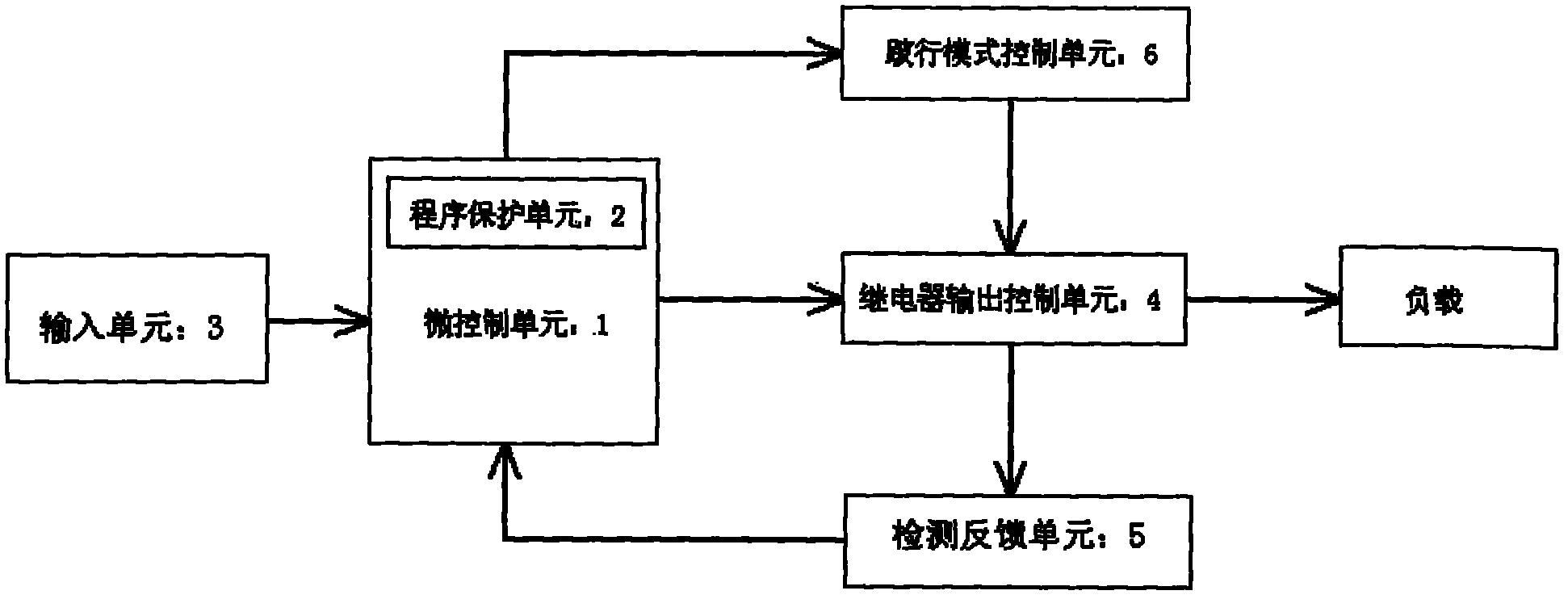
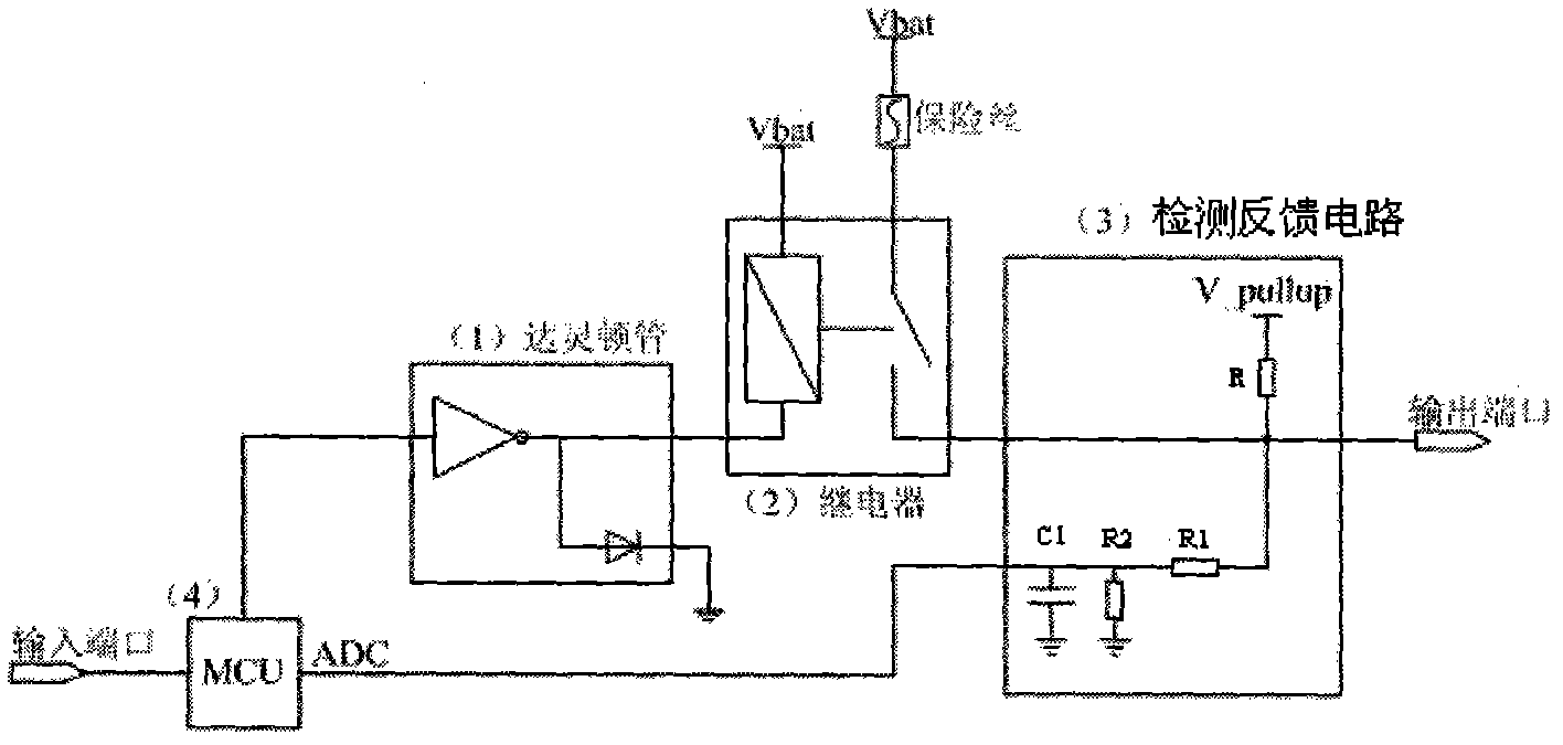
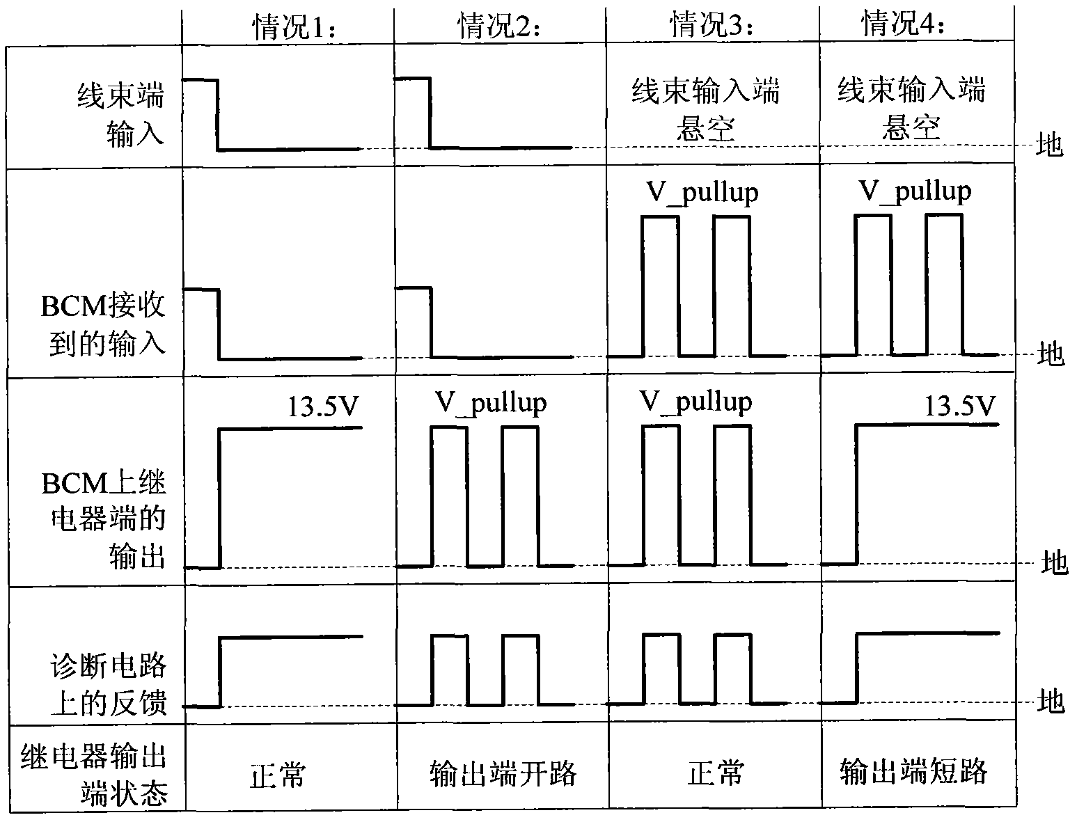
[0031] figure 1 A structural block diagram of the vehicle body control system provided by the present invention. As shown in the figure, the body control system (BCM) includes a micro control unit (MCU) 1, an input unit 3 electrically connected to the micro control unit 1 and a relay output control unit 4, and a program protection unit arranged in the micro control unit 1 2, and a detection feedback unit 5 and a limp mode control unit 6 electrically connected between the micro control unit 1 and the relay output control unit 4 . Wherein, the input unit 3 includes switches that can be operated on the vehicle, such as the up switch and down switch of the car window, the light combination switch, the wiper combination sw...


PUM


Abstract

The invention discloses an automobile body control system, comprising an input unit, a micro control unit and a claudication type control unit, wherein the input unit is used for receiving an input signal and transmitting the input signal to the micro control unit, the micro control unit is used for controlling a relay output control unit to drive a load to operate according to the input signal; and the claudication type control unit is used for controlling the relay output control unit to drive partial load to operate when the micro control unit is in failure. The automobile body control system provided by the invention is additionally provided with the claudication type control unit, and the relay output control unit is controlled to drive partial load to operate continuously when the micro control unit is in failure, thus ensuring normal use of the automobile body control system in a vehicle operating process and improving the stability of the automobile body control system.

Description

technical field [0001] The invention relates to an automobile electronic control system, in particular to a vehicle body control system with high stability which can keep part of the load and continue to work when a micro control unit breaks down. Background technique [0002] With the development of science and technology, more and more electronic technology is applied in automobiles, and the application degree of electronic technology has become an important symbol of improving the technical level of automobiles. As far as the current situation is concerned, automotive electronic technology is divided into two categories: automotive electronic control systems, such as ABS, electronically controlled fuel injection, etc.; automotive automotive electronic devices, such as automotive multimedia systems, automotive communication systems, etc. [0003] Due to the development of electronic information technology and the maturity of embedded system, LAN CAN and data bus technology...

Claims


Application Information

Patent Timeline
IPC IPC(8): G05B23/02
Inventor 高放
Owner CHERY AUTOMOBILE CO LTD
Learn More