Flight simulating system and driving unit

A flight simulation and drive unit technology, applied in the mechanical field, can solve the problems of insufficient functionality, poor reliability and lifespan, etc., and achieve the effect of simple structure, high reliability and convenient installation

Inactive Publication Date: 2011-05-18
BEIHANG UNIV
View PDF0 Cites 0 Cited by
  • Summary
  • Abstract
  • Description
  • Claims
  • Application Information

AI Technical Summary

Problems solved by technology

[0010] In order to solve the problems of poor reliability, poor life and insufficient functionality caused by the structural defects of the flight simulation system in the prior art, a preferred embodiment of the present invention proposes a flight simulation system and a drive unit

Method used


Image

  • Flight simulating system and driving unit
  • Flight simulating system and driving unit
  • Flight simulating system and driving unit

Examples


Embodiment 1

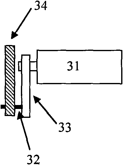
[0039] The preferred embodiment of the present invention proposes a flight simulation system, its structure is as image 3 , Figure 4 , Figure 5 It includes a motor 31, a load (not shown in the figure), and a connection mechanism. Connecting mechanism comprises active rod 33 and connecting rod 34, and active rod 33 one end is fixedly connected to the power output shaft of motor 31, and rotates with power output shaft; The other end of active rod 33 connects an end of connecting rod 34 by shaft 32; Connecting rod 34 The other end is fixedly connected to the load.

[0040] In a preferred embodiment of the present invention, the motor pushes the seat or the cockpit to move up and down through a crank linkage mechanism. When the motor is not working, such as image 3 As shown, the active rod 33 is at the lower limit position under the action of load gravity. Such as Figure 6 As shown, the active rod 33 can rotate 360 ​​degrees with the power output shaft, so that the shak...

Embodiment 2

[0051] The preferred embodiment of the present invention proposes the driving unit of the flight simulation system, its structure is as follows image 3 , Figure 4 , Figure 5 Including motor 31, connecting mechanism. The connecting mechanism includes an active rod 33 and a connecting rod 34. One end of the active rod 33 is fixedly connected to the power output shaft of the motor 31 and rotates with the power output shaft;

[0052] When the driving device is used with a load, the other end of the connecting rod 34 is fixedly connected to the load (not shown in the figure).

[0053] In a preferred embodiment of the present invention, the motor pushes the seat or the cockpit to move up and down through a crank linkage mechanism. When the motor is not working, such as image 3 As shown, the active rod 33 is at the lower limit position under the action of load gravity. Such as Figure 6 As shown, the active rod 33 can rotate 360 ​​degrees with the power output shaft, so tha...


PUM


Abstract

The invention discloses a flight simulating system and a driving unit, which belong to the field of machinery. The flight simulating system disclosed by the invention comprises a motor, a load and a connecting mechanism, wherein the connecting mechanism comprises a driving rod and a connecting rod, and one end of the driving rod is fixedly connected with a power output shaft of the motor and rotates along with the power output shaft; the other end of the driving rod is connected with one end of the connecting rod through a shaft; and the other end of the connecting rod is fixedly connected with the load. The driving unit of the flight simulating system, which is disclosed by the invention, comprises a motor and a connecting mechanism, wherein the connecting mechanism comprises a driving rod and a connecting rod, and one end of the driving rod is fixedly connected with a power output shaft of the motor and rotates along with the power output shaft; and the other end of the driving rod is connected with one end of the connecting rod through a shaft. Through a crank connecting mechanism in the invention, the buffeting amplitude and strength of the load can be flexibly controlled by the flight simulating system within a design range.

Description

technical field [0001] The invention relates to the mechanical field, in particular to a flight simulation system and a drive unit. Background technique [0002] Flight training is a high-input and high-risk industry. Therefore, with the development of technology, it tends to train pilots through flight simulation systems. This can not only reduce costs, but also greatly improve the pilot's practical ability. species and non-hazardous. when [0003] In the flight simulation system, various impact motions need to be simulated. Especially in the vertical direction, the simulation of shock signals is used when simulating landing and taxiing. The commonly used method is to shake the seat or shake the cockpit. These devices are characterized by: [0004] 1) Large load variation range: the weight in the cockpit or the weight of the pilot on the seat varies greatly, and the shaking device must have very good load characteristics; [0005] 2) The range of motion is controllabl...

Claims


Application Information

Patent Timeline
Patent Type & Authority Applications(China)
IPC IPC(8): G09B9/10G09B9/12
Inventor 葛蘅袁修干
Owner BEIHANG UNIV
Why Eureka
Try Eureka