Environment-friendly intelligent mutual inductor and mutual inductor compensation method

A transformer, an environment-friendly technology, applied in the field of transformers, can solve problems such as inability to measure with instruments, and achieve the effects of reducing manpower consumption, strong practicability, and convenient assembly

Active Publication Date: 2020-06-09
HEBEI ZHONGKAIMINGTAI ELECTRICAL EQUIPMENT CO LTD
View PDF5 Cites 0 Cited by
  • Summary
  • Abstract
  • Description
  • Claims
  • Application Information

AI Technical Summary

Problems solved by technology

[0003] In order to transmit electric energy, the power system often uses AC voltage and high current loops to send electric power to users, which cannot be directly measured by instruments

Method used


Image

  • Environment-friendly intelligent mutual inductor and mutual inductor compensation method
  • Environment-friendly intelligent mutual inductor and mutual inductor compensation method
  • Environment-friendly intelligent mutual inductor and mutual inductor compensation method

Examples


Embodiment 1

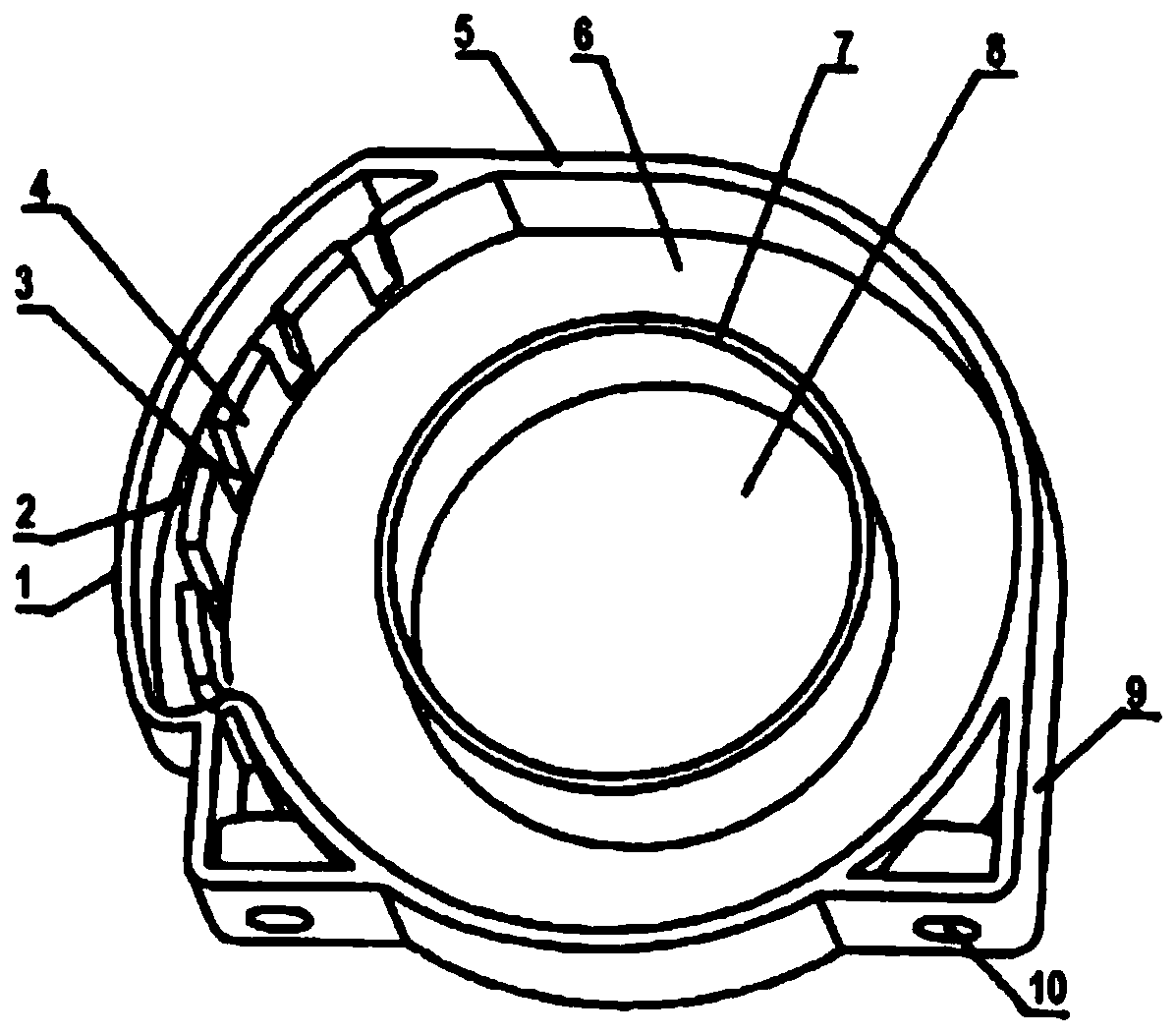
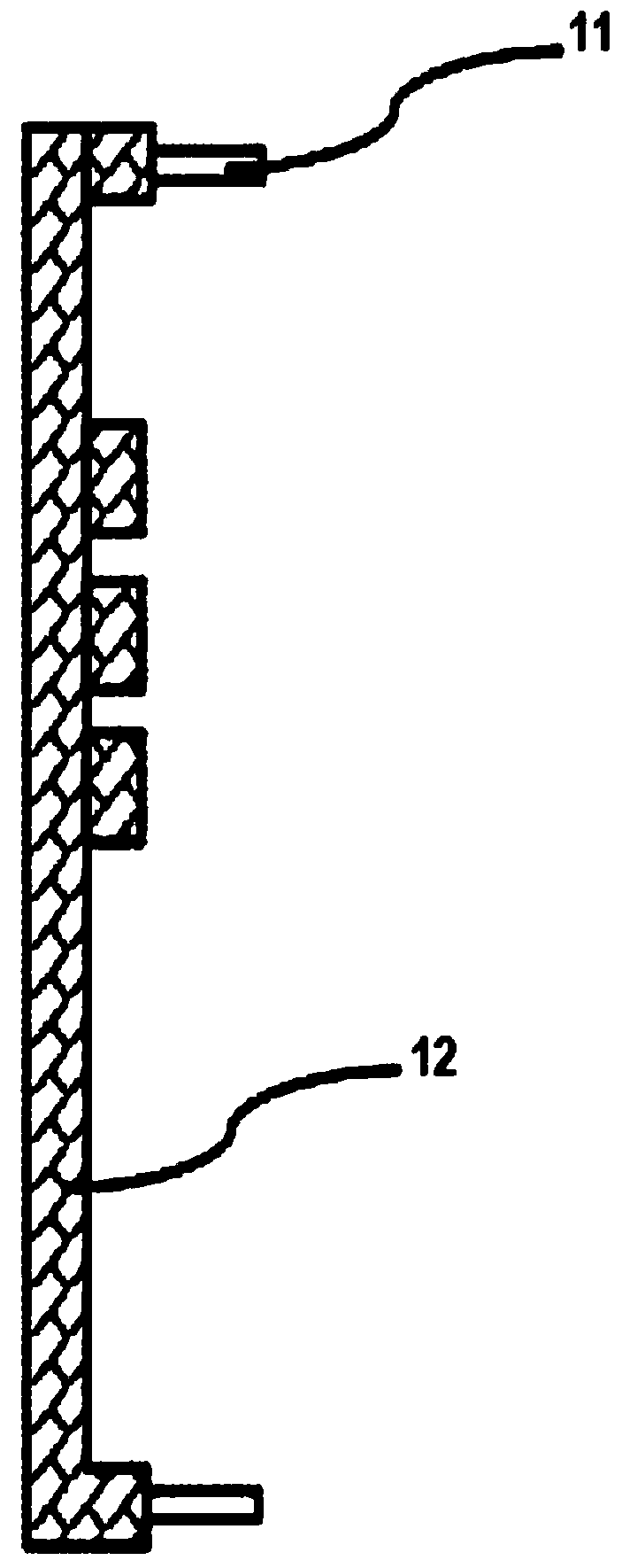
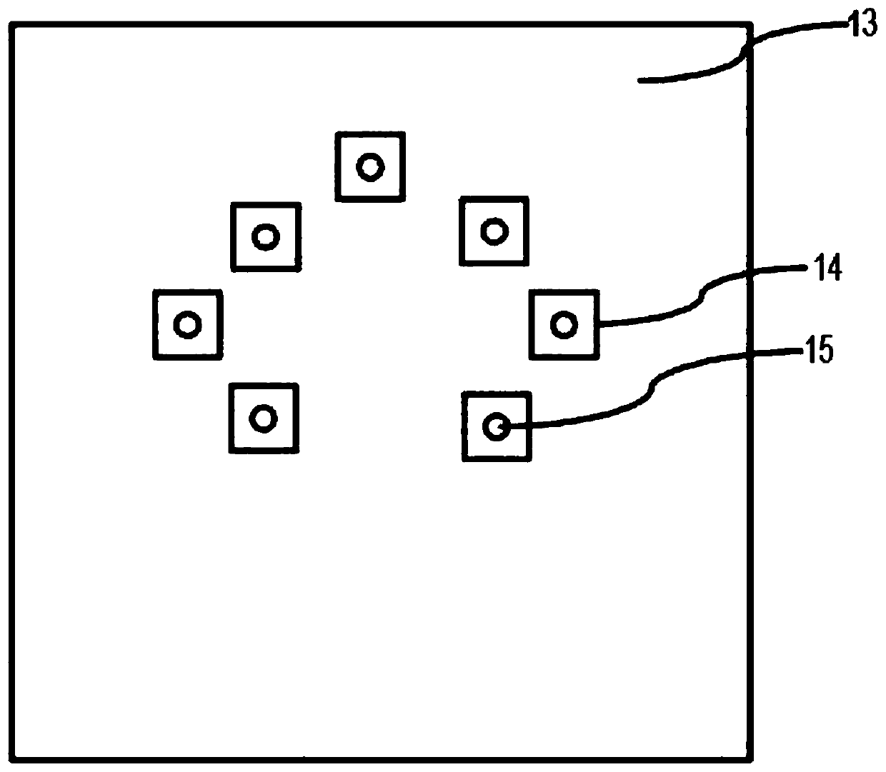
[0035] Such as figure 1 , figure 2 , image 3 , Figure 4 , Figure 5 , Figure 6 , Figure 7 and Figure 8 As shown, an environment-friendly intelligent transformer includes: a transformer, an outer casing and an inner casing; an insulating material is arranged between the outer casing and the inner casing; the transformer is placed in the inner casing; the The transformer includes: a transformer body, a delay compensation device and a saturation calculation device; the delay compensation device and the saturation calculation device are respectively signal-connected to the transformer body; the delay compensation device is used to delay the transformer Compensation; the saturation calculation device is used to calculate the saturation degree of the transformer, and controls the operation of the transformer; it is characterized in that the saturation calculation device, the method for calculating the saturation degree of the transformer performs the following steps: the...

Embodiment 2

[0042] On the basis of the previous embodiment, the intermediate matrix R is expressed as:

[0043]

[0044] Among them, the r' bit calculates the absolute value operation of the difference between two numbers.

Embodiment 3

[0046]On the basis of the previous embodiment, the outer casing is made of metal material; the outer casing includes: a left half and a right half; the left half and the right half are completely engaged to form a closed space; The left half is a side; the right half includes a top surface, a bottom surface and three sides; the side of the left half and the side wall of the right half opposite to the side of the left half have several a protruding post, the protruding post has a socket; the inner casing includes an outer ring wall, a coil slot, an inner ring wall, and a rear wire perforation; the left and right parts of the lower side of the outer ring wall each have a mounting boss and its mounting screw holes; the section of the outer ring wall above the mounting boss on the left or right side has a spaced winding groove and winding teeth, and there are leads on the outside of the outer ring wall section with winding grooves and winding teeth groove and the outer wall of the...


PUM


Abstract

The invention belongs to the technical field of mutual inductors, and particularly relates to an environment-friendly intelligent mutual inductor and a mutual inductor compensation method. The intelligent mutual inductor comprises a mutual inductor, an outer shell and an inner shell, wherein an insulating material is arranged between the outer shell and the inner shell; the mutual inductor is arranged in the inner shell; the mutual inductor comprises a mutual inductor body, a delay compensation device and a saturation calculation device; the delay compensation device and the saturation calculation device are in signal connection with the mutual inductor body; the delay compensation device is used for performing delay compensation on the mutual inductor; the saturation calculation device isused for calculating the saturation degree of the mutual inductor and controlling the mutual inductor to operate. The intelligent mutual inductor has the advantages of environmental protection, energy conservation, easy use and installation, good mutual induction performance and accurate time delay compensation.

Description

technical field [0001] The invention belongs to the technical field of transformers, and in particular relates to an environment-friendly intelligent transformer and a compensation method for the transformer. Background technique [0002] Transformer, also known as instrument transformer, is a general term for current transformer and voltage transformer. It can change high voltage into low voltage and high current into small current for measurement or protection system. Its function is mainly to convert high voltage or high current into standard low voltage (100V) or standard small current (5A or 1A, both refer to rated value) in proportion, so as to realize the standardization and miniaturization of measuring instruments, protection equipment and automatic control equipment. change. At the same time, the transformer can also be used to isolate the high-voltage system to ensure the safety of people and equipment. [0003] In order to transmit electric energy, the power sy...

Claims


Application Information

Patent Timeline
Patent Type & Authority Applications(China)
IPC IPC(8): H01F27/02H01F38/30G01R15/18
CPCG01R15/185H01F27/02H01F38/30
Inventor 董永亮
Owner HEBEI ZHONGKAIMINGTAI ELECTRICAL EQUIPMENT CO LTD
Why Eureka
Try Eureka