
Cover plate structure of battery

A battery cover and substrate technology, which is applied to structural parts, battery pack components, circuits, etc., can solve the problems of complex procedures and poor sealing effect, and achieve the effects of simple procedures, prolonged service life, and avoidance of deformation.

Inactive Publication Date: 2011-05-18
WUXI FUHONG TECH
View PDF8 Cites 4 Cited by
  • Summary
  • Abstract
  • Description
  • Claims
  • Application Information

AI Technical Summary

Problems solved by technology

[0009] The present invention proposes a battery cover structure in order to solve the problems in the prior art that the lithium-ion battery cover plate has poor sealing effect during formation, complicated procedures, and the finished battery is prone to bulging and storm valves when the internal air pressure is too high.

Method used


Image

  • Cover plate structure of battery
  • Cover plate structure of battery
  • Cover plate structure of battery

Examples


Embodiment 1

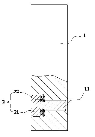
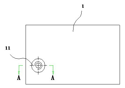
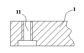
[0034] The threaded through hole 11 is also used as a liquid injection hole, and the electrolyte is injected into the battery case through the threaded through hole 11 .

[0035] When this structure is adopted, when the battery is formed, the screw 21 can be half-screwed into the threaded through hole 11, so that the screw 21 is in a half-tightened state; during the formation process, it is not necessary to use adhesive tape and cotton to seal the opening, and the sealing effect is good, and The process is simple and easy to operate; after the formation is completed, the screw 21 can be tightened directly, and the sealing ring 22 can seal the thread gap that may exist between the screw 21 and the liquid injection hole 11 under the pressure of the screw 21, and the sealing effect is good. The screw 21 resources can be reused, and the whole process does not need to remove the adhesive tape or cotton, which improves the production efficiency and avoids the defect of metal shell de...

Embodiment 2

[0038] Such as Figure 5 As shown, the substrate 1 is further provided with a liquid injection hole 12 for injecting liquid into the battery case. At this time, the liquid injection hole 12 is a conventional structure in the prior art, and is finally sealed by an interference-fit steel ball; the threaded through hole 11 is sealed and assembled by the sealing device 2 .

[0039] With the battery cover plate structure, due to the arrangement of the threaded through hole 11 and the sealing device 2, the air pressure inside the battery can be released, thereby avoiding problems such as battery bulging and explosion valves, and prolonging the service life of the battery.

Embodiment 3

[0041] Such as Image 6As shown, the substrate 1 is further provided with a liquid injection hole 13 , which has the same structure as the threaded through hole 11 and is also sealed and assembled by the sealing device 2 . With this structure, it has double safety protection functions of both explosion-proof and pressure relief.


PUM


Abstract

The invention relates to a cover plate structure of a battery, comprising a base plate and a sealing device, wherein the base plate is provided with a threaded through hole; the sealing device is hermetically assembled and connected with the threaded through hole of the base plate. The cover plate structure has the advantages of good closing effect in a formation process, simple process, easy operation, good sealing effect, resource reusability and enhanced production efficiency; in addition, a screw and the threaded through hole are separated from each other or generate a gap due to overhigh internal air pressure in the using process of the battery so that the internal air pressure of the battery is released and the phenomena, i.e. shell bulge, valve bulge, and the like of the battery are prevented, and thereby the service life of the battery is prolonged.

Description

technical field [0001] The invention relates to a lithium ion battery, in particular to a battery cover plate structure of the lithium ion battery. Background technique [0002] A lithium-ion battery includes a metal casing, a battery cell, and a cover plate, wherein the cover plate is used to package the metal casing loaded into the battery cell. The general procedures for the processing and manufacturing of lithium-ion batteries are as follows: firstly, the battery cell is installed in the metal case, and the cover plate is sealed and connected to the opening of the metal case by means of laser welding, etc., and then the electrolyte is injected into the metal case, and the After the battery cell is fully infiltrated with the electrolyte, the battery is formed. [0003] In order to inject the electrolyte into the metal case, a liquid injection hole is usually opened on the cover plate of the lithium-ion battery. When injecting liquid into the metal shell, inject the elec...

Claims


Application Information

Patent Timeline
IPC IPC(8): H01M2/04H01M2/08H01M2/36
CPCY02E60/12Y02E60/10
Inventor 陈宇澄许天军田宏国
Owner WUXI FUHONG TECH
Learn More