
High-power battery device

A battery device and high-power technology, applied in battery circuit devices, circuit devices, output power conversion devices, etc., can solve problems such as high voltage, cost and volume increase, and power supply time reduction

Active Publication Date: 2011-05-18
HAWUN ELECTRONICS CO LTD
View PDF4 Cites 24 Cited by
  • Summary
  • Abstract
  • Description
  • Claims
  • Application Information

AI Technical Summary

Problems solved by technology

[0002] In hybrid electric vehicles, dual-mode vehicles, pure electric vehicles, home energy systems, distributed peak-shaving power stations, and all equipment powered by series batteries, many applications must use multiple batteries in series due to the low voltage of a single battery. The application of batteries (especially lithium batteries) is becoming more and more extensive and as time goes by, the problems caused by the series connection of batteries are gradually exposed. For example, the damage of any battery in the series connection will cause the interruption of power supply. It is not suitable for applications that cannot be powered off; at this time, even if a backup battery is used, the cost and size will increase significantly
In addition, because each battery is different, it is difficult to fully charge and discharge each battery when charging and discharging batteries in series. After repeated charging and discharging for a long time, it is easy to produce a battery that is not fully charged and will emit light when discharging. , at this time the entire battery system cannot supply power, and the power supply time will be greatly reduced compared with the new battery
At the same time, the battery voltage is high when it is put into use after charging, and the voltage is low after discharging, which is not conducive to the optimization of the subsequent circuit and the improvement of efficiency

Method used


Image

  • High-power battery device
  • High-power battery device
  • High-power battery device

Examples


Embodiment Construction

[0035] Embodiments of the present invention will be further described below in conjunction with the accompanying drawings.

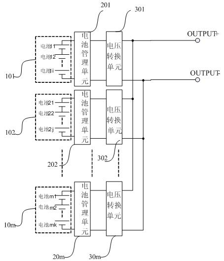
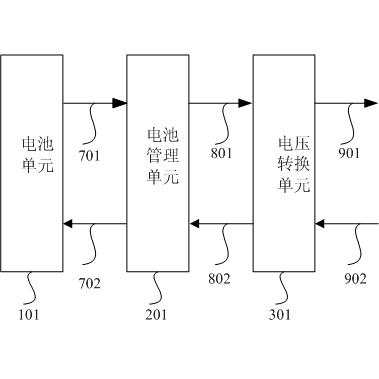
[0036] Such as figure 1 As shown, in an embodiment of a high-power battery device of the present invention, the high-power battery includes a plurality (m) of battery cells (101, 102...10m), and each battery cell is connected in parallel with a Battery management unit (201, 202...20m), the battery unit provides voltage and current to the outside through the battery management unit; a voltage conversion unit (301, 302...30m) is connected to the output end of each battery management unit above The function of the above-mentioned voltage conversion unit is to convert the voltage provided by the battery unit into a voltage set according to needs and provide it to the outside. In this embodiment, the set voltage is the rated output voltage of the high-power battery device. In this embodiment, the above-mentioned first battery unit 101 includes a single-cell ...


PUM


Abstract

The invention relates to a high-power battery device which comprises a plurality of battery units, battery management units and a plurality of voltage conversion units. Each battery unit is formed by a single battery or a plurality of series connected single batteries, the battery management units are respectively connected in parallel with the output ends of the plurality of battery units, the plurality of voltage conversion units are respectively connected with the output ends of the battery management units and output set voltages, the output ends of the plurality of voltage conversion units are connected in parallel, each voltage conversion unit has an output end current-sharing signal to ensure little difference among output powers of the voltage conversion units. The voltage conversion units are bidirectional, which means that the voltage conversion unit can supply energy for the output ends when the batteries supply power and can charge the batteries when an additional requiredvoltage is applied to the output ends. The high-power battery device has the advantages of not causing abnormal power supply due to difference of the batteries and keeping output voltage stable as required.

Description

technical field [0001] This invention relates to rechargeable batteries, and more particularly, to a high power battery device. Background technique [0002] In hybrid electric vehicles, dual-mode vehicles, pure electric vehicles, home energy systems, distributed peak-shaving power stations, and all equipment powered by series batteries, many applications must use multiple batteries in series due to the low voltage of a single battery. The application of batteries (especially lithium batteries) is becoming more and more extensive and as time goes by, the problems caused by the series connection of batteries are gradually exposed. For example, the damage of any battery in the series connection will cause the interruption of power supply. It is not suitable for applications that cannot be powered off; in this case, even if a backup battery is used, the cost and size will increase significantly. In addition, because each battery is different, it is difficult to fully charg...

Claims


Application Information

Patent Timeline
Patent Type & Authority Applications(China)
IPC IPC(8): H02J7/34H02J7/00H02M3/335
Inventor 吕文硕
Owner HAWUN ELECTRONICS CO LTD
Learn More