Fuel cell system and its operation method

a fuel cell and operation method technology, applied in the direction of electrical generators, emergency supply, sustainable buildings, etc., can solve the problems of difficult driving insufficient power supply to the load power source, etc., and achieve the effect of low-efficiency operation

Active Publication Date: 2012-09-11
TOYOTA JIDOSHA KK
View PDF11 Cites 8 Cited by
  • Summary
  • Abstract
  • Description
  • Claims
  • Application Information

AI Technical Summary

Benefits of technology

[0013]When such a constitution is employed, the output voltage of the fuel cell can be kept constant even in a case where the output voltage of the fuel cell is changed in accordance with the change of the output demand from the load power source. Therefore, the generation of electricity charge or discharge due to the change of the output voltage of the fuel cell can be suppressed, so that the precision of the output power control of the fuel cell can be improved. Moreover, even when the output demand from the load power source changes, the output voltage of the fuel cell can be kept at the minimum drive voltage as it is, so that the maximum temperature raising effect by the low-efficiency operation can constantly be obtained.
[0015]When such a constitution is employed and there is not any output demand from the load power source, the output voltage of the fuel cell can be set to the value less than the minimum drive voltage of the load power source to realize the low-efficiency operation. Therefore, the power energy used for driving the load power source can be converted into thermal energy and effectively utilized to efficiently perform the warm-up, and a temperature raising time can be shortened.
[0018]In a case where such a constitution is employed, when the operation mode of the vehicle driving motor is the neutral mode or the parking mode but the back electromotive voltage of the vehicle driving motor is larger than the predetermined reference voltage (e.g., a system voltage during the low-efficiency operation), driving and controlling of the vehicle driving motor can be continued. In consequence, the damage of an inverter due to the back electromotive voltage of the vehicle driving motor or the like can be suppressed.
[0019]According to the present invention, there can be provided the fuel cell system capable of realizing both the driving of the load power source and the warm-up by the low-efficiency operation.

Problems solved by technology

Therefore, if a low-efficiency operation is performed in the same manner as in a conventional example to prioritize the temperature rise of the fuel cell, the power cannot sufficiently be supplied to the load power source, and it might be difficult to drive the load power source.

Method used


Image

  • Fuel cell system and its operation method
  • Fuel cell system and its operation method
  • Fuel cell system and its operation method

Examples


Embodiment Construction

[0026]Hereinafter, a fuel cell system according to an embodiment of the present invention will be described with reference to the drawings. In the present embodiment, an example in which the present invention is applied to a car-mounted power generation system of a fuel cell vehicle will be described.

[0027]First, a constitution of a fuel cell system 1 according to the embodiment of the present invention will be described with reference to FIGS. 1 to 3.

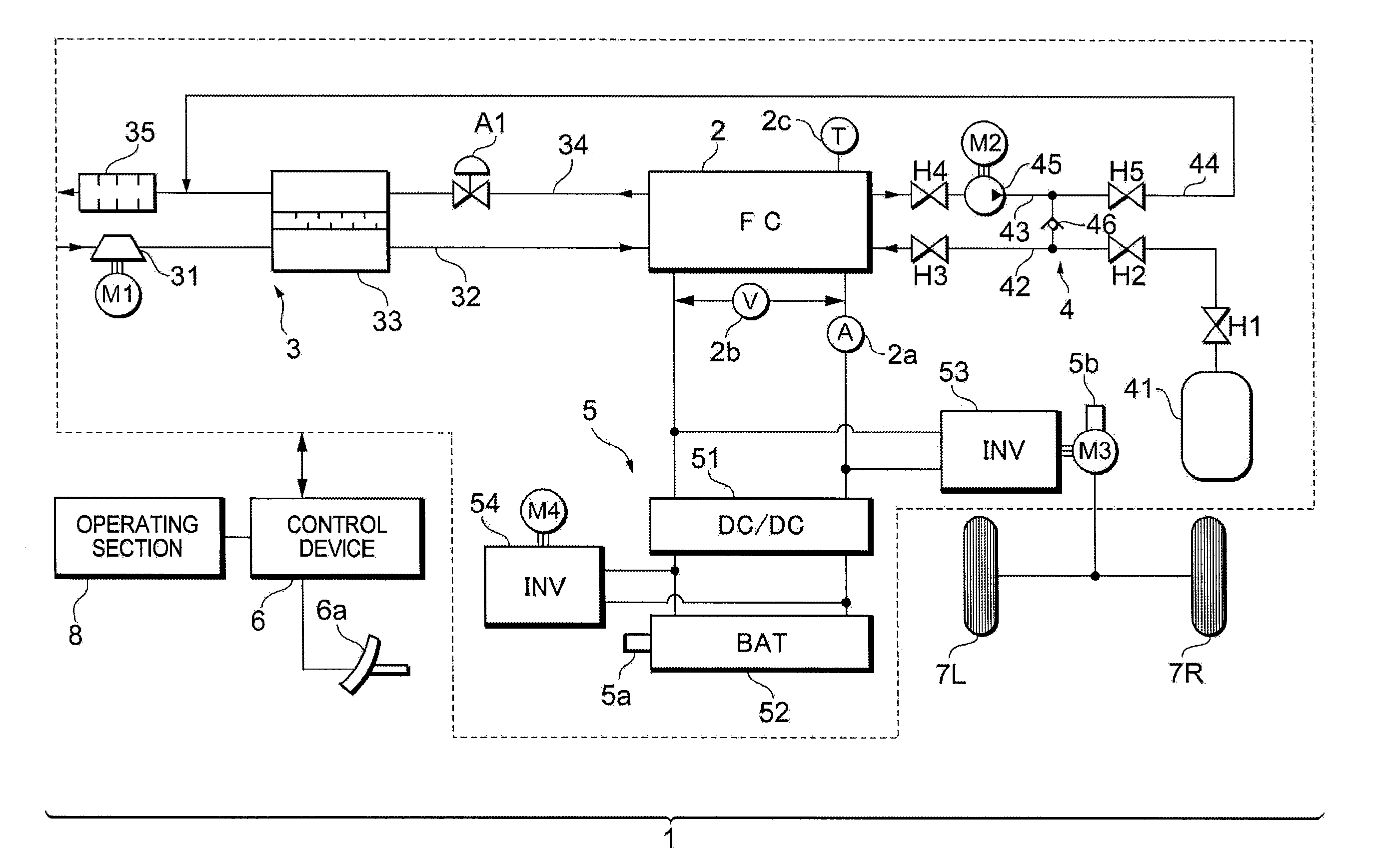
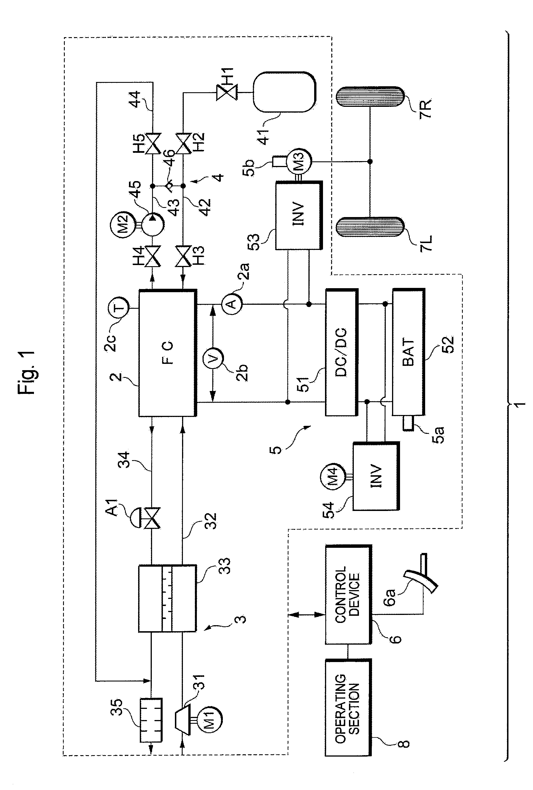
[0028]As shown in FIG. 1, the fuel cell system 1 according to the present embodiment includes a fuel cell 2 which receives the supply of a reactant gas (an oxidizing gas and a fuel gas) to generate electricity; an oxidizing gas piping system 3 which supplies air as the oxidizing gas to the fuel cell 2; a fuel gas piping system 4 which supplies a hydrogen gas as the fuel gas to the fuel cell 2; a power system 5 which charges or discharges the power of the system; a control device 6 which generally controls the whole system and the like....


PUM

PropertyMeasurementUnit
power lossaaaaaaaaaa
output voltageaaaaaaaaaa
drive voltageaaaaaaaaaa

Abstract

A fuel cell system includes: a fuel cell which generates electricity; and control means which supplies an output power from the fuel cell to a predetermined load power source while realizing a low-efficiency operation of the fuel cell, thereby driving and controlling the load power source. The control means sets the output voltage of the fuel cell during the low-efficiency operation to a value not smaller than the minimum drive voltage of the load power source.

Description

[0001]This is a 371 national phase application of PCT / JP2007 / 069405 filed 27 Sep. 2007, which claims priority to Japanese Patent Application No. 2006-286219 filed 20 Oct. 2006, the contents of which are incorporated herein by reference.TECHNICAL FIELD[0002]The present invention relates to a fuel cell system and its operation method.BACKGROUND ART[0003]Heretofore, a fuel cell system including a fuel cell for receiving the supply of a reactant gas (a fuel gas and an oxidizing gas) to generate electricity has been suggested and put to practical use. At present, there has been suggested a technology in which a low-efficiency operation (an operation in a state of a power generation efficiency lower than that of a normal operation) of the fuel cell is performed to convert the energy of the supplied reactant gas into more thermal energy, thereby raising the temperature of the fuel cell.[0004]The low-efficiency operation of the fuel cell is frequently performed “during starting” or “during ...

Claims


Application Information

Patent Timeline
Patent Type & Authority Patents(United States)
IPC IPC(8): H01M8/04
CPCH01M8/04268H01M8/04365H01M8/04559H01M8/04589H01M8/04626H01M8/04753H01M8/0488H01M8/0491H01M8/0494H01M8/04731H01M2250/10H01M2250/20Y02B90/14Y02T90/32Y02E60/50Y02B90/10Y02T90/40H01M8/04H01M8/10
Inventor IMANISHI, HIROYUKIMANABE, KOTAOGAWA, TOMOYA
Owner TOYOTA JIDOSHA KK
Why Eureka
Try Eureka