Design method of permanent magnet motor capable of reducing cogging effect and permanent magnet motor

A technology of permanent magnet motor and cogging effect, which is applied in the direction of magnetic circuit shape/style/structure, salient pole, etc., can solve the problem of permanent magnet motor torque constant/thrust constant decrease, and achieve reduction of cogging torque/ Effects of cogging force, peak reduction, and harmonic component reduction

Inactive Publication Date: 2011-05-18
天津蓝马工业工程技术有限公司 +2
View PDF3 Cites 12 Cited by
  • Summary
  • Abstract
  • Description
  • Claims
  • Application Information

AI Technical Summary

Problems solved by technology

[0005] The skewed slot or skewed pole structure is a widely used method of reducing cogging, by tilting the stator laminations or the mover magnets at a certain angle, ideally, the coggi

Method used


Image

  • Design method of permanent magnet motor capable of reducing cogging effect and permanent magnet motor
  • Design method of permanent magnet motor capable of reducing cogging effect and permanent magnet motor
  • Design method of permanent magnet motor capable of reducing cogging effect and permanent magnet motor

Examples


Embodiment Construction

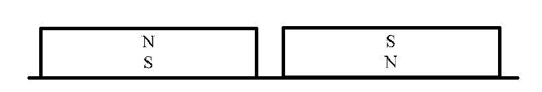
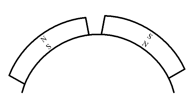
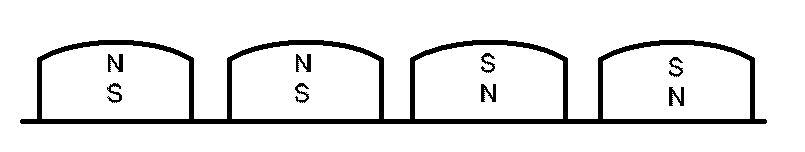
[0061] see Figure 3-6, the present invention selects an appropriate curved surface permanent magnet, or a permanent magnet that is properly chamfered, and divides the single permanent magnet of each magnetic pole into several permanent magnet small pieces along the circumferential direction of the rotary motor or the moving direction of the linear motor. The permanent magnets are arranged on the surface of the stator or the mover at a certain distance, which can reduce the peak value of single-tooth cogging torque / cogging force, reduce complex harmonic components, and effectively reduce the cogging torque / cogging force of surface permanent magnet motors. cogging forces and reduce costs.

[0062] Using the analytical or numerical calculation method of the electromagnetic field, with the goal of minimizing the cogging torque / cogging force of the permanent magnet motor, the single permanent magnet of each magnetic pole is optimally divided into two parts along the circumferentia...


PUM


Abstract

The invention discloses a design method of a permanent magnet motor capable of reducing cogging effect and a permanent magnet motor. Each magnetic pole in the permanent magnet motor at least comprises two permanent magnets with the same magnetic pole directions, and corresponding parameters of permanent magnets subjected to circular arc top surface or chamfering treatment when the cogging effect of the permanent magnet motor is the minimum are acquired by a finite element computation method, wherein the parameters of the permanent magnets mainly comprise the number n (n>=2) of the permanent magnets the magnetic pole directions of which are the same in each magnetic pole, the width of each permanent magnet, and the distance between two adjacent permanent magnets. The permanent magnet motor disclosed by the invention can reduce cogging torque/cogging force peak value borne by a single tooth and reduce complicated harmonic components, thereby effectively reducing the cogging torque/cogging force of a surface type permanent magnet motor.

Description

technical field [0001] The invention relates to the technical field of motors, in particular to a method for reducing the cogging effect of a permanent magnet motor and the permanent magnet motor. Background technique [0002] Due to its compact structure, high torque density, high efficiency, non-excitation heating, etc., permanent magnet motors have been more and more widely used in industry. [0003] In the permanent magnet motor, the pole pairs of permanent magnets are arranged alternately according to N and S poles. For permanent magnet linear motors, see figure 1 , permanent magnet rotating motor see figure 2 . see Figure 7 , when a single tooth of the permanent magnet motor is close to the two ends of the permanent magnet, the amplitude of the cogging torque / cogging force is the largest. When the center line of the tooth coincides with the permanent magnet, the cogging torque / tooth The cogging force is zero. In the prior art, due to the fixed circumferential bro...

Claims


Application Information

Patent Timeline
IPC IPC(8): H02K1/08
Inventor 陈学东李健张玲莉曾理湛陈霈
Owner 天津蓝马工业工程技术有限公司
Why Eureka
Try Eureka