Piezoelectric ceramic driving power supply and control method thereof

A piezoelectric ceramic drive, piezoelectric ceramic technology, applied in piezoelectric effect/electrostrictive or magnetostrictive motors, control/regulation systems, generators/motors, etc., can solve problems such as demand

Inactive Publication Date: 2011-05-18
BEIJING INSTITUTE OF TECHNOLOGYGY
View PDF2 Cites 27 Cited by
  • Summary
  • Abstract
  • Description
  • Claims
  • Application Information

AI Technical Summary

Problems solved by technology

[0008] The purpose of the present invention is to solve the demand for piezoelectric ceramic drive power supply with low DC voltage input in practical...

Method used


Image

  • Piezoelectric ceramic driving power supply and control method thereof
  • Piezoelectric ceramic driving power supply and control method thereof
  • Piezoelectric ceramic driving power supply and control method thereof

Examples


Embodiment Construction

[0075] In order to better illustrate the purpose and advantages of the present invention, the specific implementation manners of the present invention will be further described in detail below in conjunction with the accompanying drawings and embodiments.

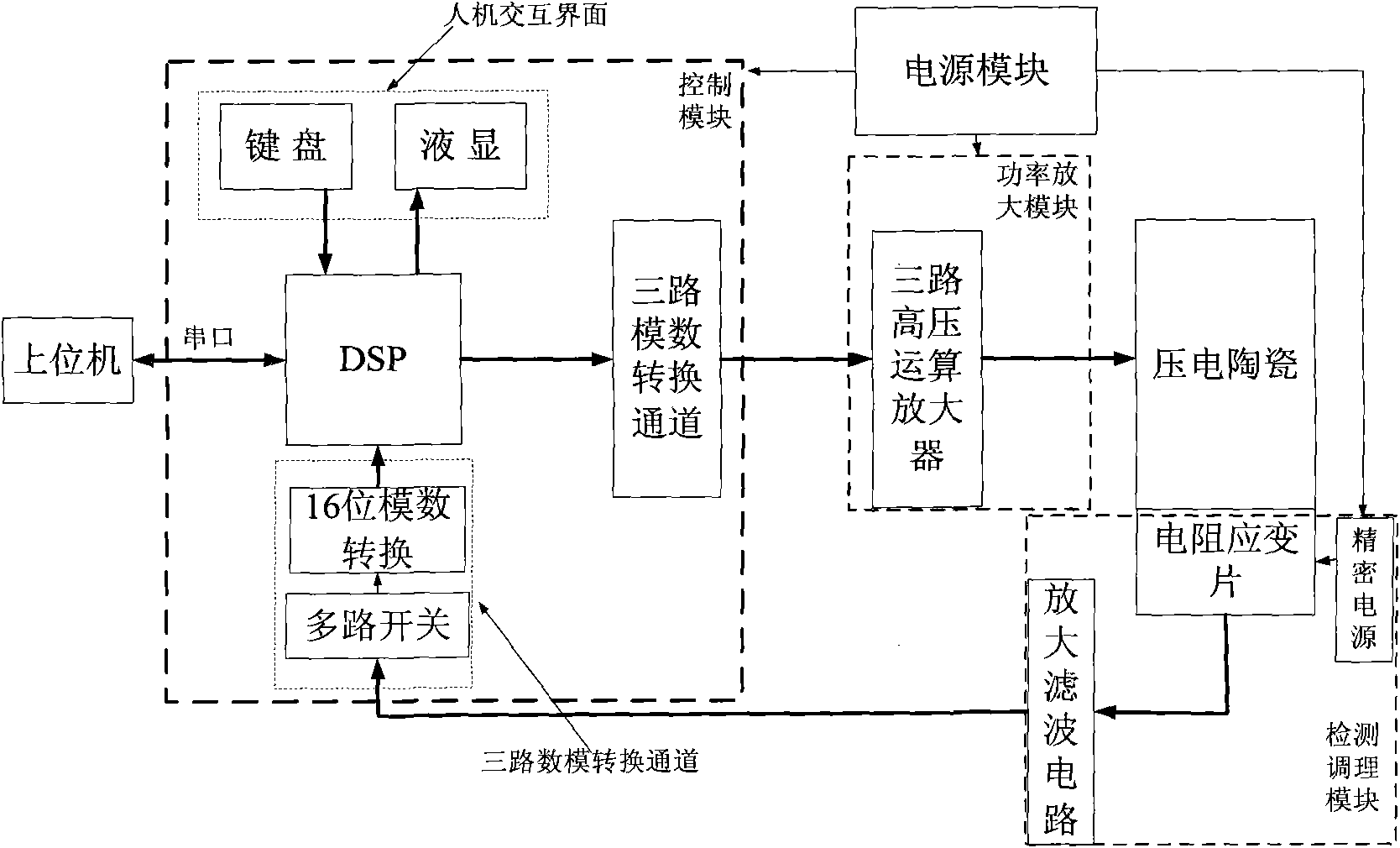
[0076] A piezoelectric ceramic driving power supply, including a power supply module, a control module, a power amplification module and a detection and conditioning module, such as figure 1 shown.

[0077] (1) Power supply module: provide the voltage required for the work of several other modules.

[0078] Includes providing stable ±15V and 200V DC voltages. The output of the power module is respectively connected with several other modules.

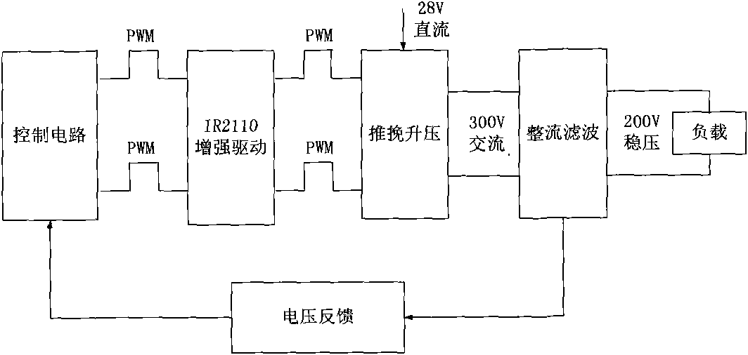
[0079] Among them, the ±15V voltage is directly converted by the voltage conversion chip. 200V DC voltage is provided by the designed switching power supply. The structure of switching power supply is as follows: image 3 As shown, a push-pull boost circuit is used to adjust the...


PUM


Abstract

The invention belongs to the technical field of a piezoelectric ceramic driving power supply and relates to a piezoelectric ceramic driving power supply and a control method thereof. The driving power supply specifically comprises a power supply module, a control module, a power amplification module and a detection and regulation module, wherein a piezoelectric ceramic self-adaptive time-varying sliding mode control method is designed for a DSP (Digital Signal Processor) controller of the control module so as to realize the accurate control on the output displacement of a piezoelectric ceramic actuator. The piezoelectric ceramic driving power supply and the control method thereof can be used under the action of low DC voltage input, have the advantages of wide frequency response and high precision, can overcome the nonlinear characteristic of the piezoelectric ceramic, can provide three-way driving voltage output to simultaneously provide mutually independent driving voltage for 1-3 piezoelectric ceramic working platforms, and can be widely used in high-precision pointing and tracking of airborne and vehicle-mounted radar antennae, thereby having fine application prospects.

Description

technical field [0001] The invention belongs to the technical field of piezoelectric ceramic driving power supply, and relates to a piezoelectric ceramic driving power supply and a control method thereof. Background technique [0002] As an ideal nanometer micro-displacement element, piezoelectric ceramics have the characteristics of small size, high displacement resolution, high frequency response, no noise, no heat, etc., and are widely used in micro-machine manufacturing, ultra-precision machining, aerospace, robotics and other fields. [0003] The driving power supply is used to provide driving voltage for the piezoelectric ceramics, and the piezoelectric ceramics can realize precise positioning through the control voltage. [0004] In principle, driving power can be divided into two types: charge (current) control type and voltage control type. The charge-controlled driving power supply is based on the principle of charging capacitors, which can effectively improve the...

Claims


Application Information

Patent Timeline
IPC IPC(8): H02N2/06H02M3/335
Inventor 刘向东赖志林陈振魏宏刚惠德学
Owner BEIJING INSTITUTE OF TECHNOLOGYGY
Why Eureka
Try Eureka