Lifting and swiveling structure

A technology of lifting and rotating and steel balls, which is applied to stools, other seating furniture, household appliances, etc., can solve problems such as rust, waste of materials, lifting and rotating problems, and achieve convenient use, long service life and structural design simple and reliable effect

Inactive Publication Date: 2011-05-25
镇江浩博航空铁道设备研发有限公司
View PDF7 Cites 2 Cited by
  • Summary
  • Abstract
  • Description
  • Claims
  • Application Information

AI Technical Summary

Problems solved by technology

Since the screw and nut are mainly made of metal materials, the thread on the screw is directly on the body, which is easy to wear and rust. After a long time of use, there will be phenomena such as lifting and shaking, poor rotation, and increased noise. , such as the Chinese patent No. 99229074.3, which changes the thread of the swivel chair lifting rod to be wound on the screw bod

Method used


Image

  • Lifting and swiveling structure
  • Lifting and swiveling structure

Examples


Embodiment Construction

[0015] The present invention will be described in further detail below in conjunction with the accompanying drawings and specific embodiments.

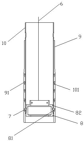
[0016] Such as figure 1 , the lifting and rotating structure includes a traction component 6, a steel ball 7, a steel ball locking disc 8, a base sleeve 9, and a steel ball locking sleeve 10; the traction component 6 is connected with the steel ball locking disc 8, and the base sleeve 9 is Cylindrical sleeves with upper and lower openings, the base sleeve 9 is set outside the steel ball locking sleeve 10; The hole 91 of the steel ball locking disc 8 is set in the steel ball locking sleeve 10, the steel ball 7 is provided on the ramp 81 of the steel ball locking disc 8, and the steel ball locking sleeve 10 is located at the bottom of the same horizontal plane. The hole 101 matched with the steel ball 7 is provided with a groove 82 on the upper part of the steel ball locking disc 8 . The base sleeve 9 has five holes 91 in the longitud...


PUM


Abstract

The invention relates to a lifting and swiveling structure, which comprises a pulling part (6), steel balls (7), a steel ball-locking disc (8), a pedestal sleeve (9) and a steel ball-locking sleeve (10); the pulling part (6) is connected with the steel ball-locking disc (8), and the pedestal sleeve (9) is sleeved on the steel ball-locking sleeve (10); holes (91) matched with the steel balls (7) are arranged on a plurality of levels of the pedestal sleeve (9); the steel ball-locking disc (8) is arranged in the steel ball-locking sleeve (10), the steel balls (7) are arranged on a slope (81) of the steel ball-locking disc (8), the lower part of the steel ball-locking sleeve (10) is provided with holes (101) matched with the steel balls (7), the holes (101) are positioned on the same level, and the upper part of the steel ball-locking disc (8) is provided with a groove (82).

Description

technical field [0001] The invention relates to a lifting and rotating structure, which is mostly used on the driver's and passenger's seats on aviation, ships (submarines), high-speed trains, automobiles and other vehicles for height adjustment and rotation positioning. Background technique [0002] Existing seat elevating and rotating mechanism realizes elevating and rotating mostly by the elevating rod that screw rod and nut are formed. Since the screw and nut are mainly made of metal materials, the thread on the screw is directly on the body, which is easy to wear and rust. After a long time of use, there will be phenomena such as lifting and shaking, poor rotation, and increased noise. , as the Chinese patent that the patent No. is 99229074.3, it is to change the screw thread of the swivel chair lifting rod into winding on the screw rod body with metal wire, and simultaneously the nut cover is made of wear-resistant, compressive nylon material instead. Although it has...

Claims


Application Information

Patent Timeline
IPC IPC(8): A47C3/24A47C7/00B60N2/16
Inventor 黄湘勋
Owner 镇江浩博航空铁道设备研发有限公司
Why Eureka
Try Eureka