Multi-rotor unmanned aerial vehicle

A multi-rotor UAV and rotor technology, applied in the field of aircraft, can solve problems such as the inability to meet the performance requirements of multi-rotor UAVs, the reduction of forward flight speed, and the increase in power consumption, and achieve simple and reliable structural design and high forward flight speed. Improve and reduce the effect of air resistance

Active Publication Date: 2019-08-20
GOERTEK ROBTICS CO LTD
View PDF7 Cites 2 Cited by
  • Summary
  • Abstract
  • Description
  • Claims
  • Application Information

AI Technical Summary

Problems solved by technology

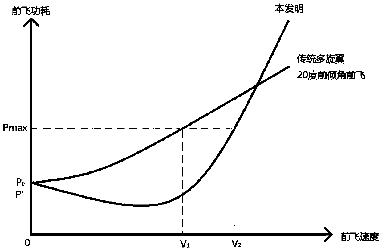
That is to say, the greater the forward tilt angle, the greater the horizontal thrust. However, the power consumption increases and the maximum forward flight speed becomes smaller, which cannot meet the current people's increasingly high performance requirements for multi-rotor drones.

Method used


Image

  • Multi-rotor unmanned aerial vehicle
  • Multi-rotor unmanned aerial vehicle
  • Multi-rotor unmanned aerial vehicle

Examples


Embodiment Construction

[0026] The following will clearly and completely describe the technical solutions in the embodiments of the present invention with reference to the accompanying drawings in the embodiments of the present invention. Obviously, the described embodiments are only part of the embodiments of the present invention, not all of them. Based on the embodiments of the present invention, all other embodiments obtained by persons of ordinary skill in the art without creative efforts fall within the protection scope of the present invention.

[0027] It should be noted that all directional indications (such as up, down, left, right, front, back...) in the embodiments of the present invention are only used to explain the relationship between the components in a certain posture (as shown in the accompanying drawings). Relative positional relationship, movement conditions, etc., if the specific posture changes, the directional indication will also change accordingly. In the description of the ...


PUM


Abstract

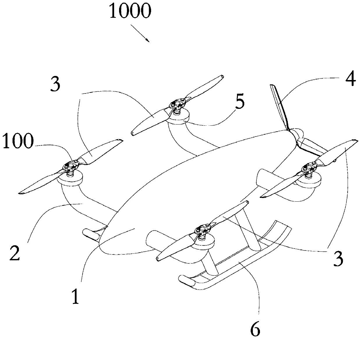
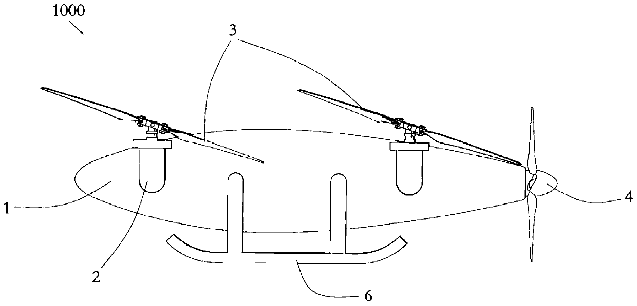
The invention discloses a multi-rotor unmanned aerial vehicle which comprises a vehicle body, a plurality of lifting rotors and a forward rotor, and the lifting rotors are configured to generate a lifting driving force for overcoming gravity in a lifting or level flight process of the multi-rotor unmanned aerial vehicle; the forward rotor is configured to generate a horizontal driving force for pushing or pulling the multi-rotor unmanned aerial vehicle to advance; the plurality of lifting rotors are respectively connected with the vehicle body and are distributed on the peripheral side of thevehicle body; the forward rotor is connected with the vehicle body and arranged at the head part or the tail part of the vehicle body; the multi-rotor unmanned aerial vehicle is provided with flappingconnecting mechanisms used for enabling each lifting rotor to be connected with the vehicle body in a flapping mode. The multi-rotor unmanned aerial vehicle can fly under the condition that the rotating plane/propeller disc plane of the lifting rotor is a negative rake angle by means of cooperation of the lifting rotors, the forward rotor and the flapping connecting mechanisms; power consumptionis reduced, and meanwhile, the maximum forward flight speed of the multi-rotor unmanned aerial vehicle is increased.

Description

technical field [0001] The invention relates to the technical field of aircraft, in particular to a multi-rotor unmanned aerial vehicle. Background technique [0002] When the existing quadrotor aircraft is flying forward, the plane of the paddle disc needs to bow forward to form a certain forward angle (greater than 0°) in order to generate the thrust required for horizontal flight. However, according to the calculation results of forward flight power consumption and forward flight speed, it shows that the forward flight power consumption increases with the increase of the propeller disc plane forward tilt angle. In addition, the larger the forward tilt angle, the smaller the vertical component of the aerodynamic resultant force on the rotor, so power consumption must be increased in order to overcome gravity. In addition, if the maximum power of the aircraft engine is constant, the greater the forward tilt angle of the paddle disc plane, the lower the maximum forward flig...

Claims


Application Information

Patent Timeline
Patent Type & Authority Applications(China)
IPC IPC(8): B64C27/08B64C27/37
CPCB64C27/08B64C27/37B64U50/19B64U10/10B64U30/20B64U50/13
Inventor 颜安韩伟张璐石翔
Owner GOERTEK ROBTICS CO LTD
Why Eureka
Try Eureka