
Measuring method for non-contact steel rail sagging surface

A measurement method and non-contact technology, which can be used in measurement devices, railway vehicle shape measuring instruments, photogrammetry/video surveying, etc., and can solve problems such as low accuracy

Inactive Publication Date: 2011-05-25
NANJING UNIV
View PDF4 Cites 4 Cited by
  • Summary
  • Abstract
  • Description
  • Claims
  • Application Information

AI Technical Summary

Problems solved by technology

Obviously, it is difficult to ensure that the ground on site is level, and there is a large error in the measurement datum of the rail surface and the vertical surface of the rail obtained from this, so such an overrun measurement method is of low accuracy

Method used


Image

  • Measuring method for non-contact steel rail sagging surface
  • Measuring method for non-contact steel rail sagging surface
  • Measuring method for non-contact steel rail sagging surface

Examples


Embodiment Construction

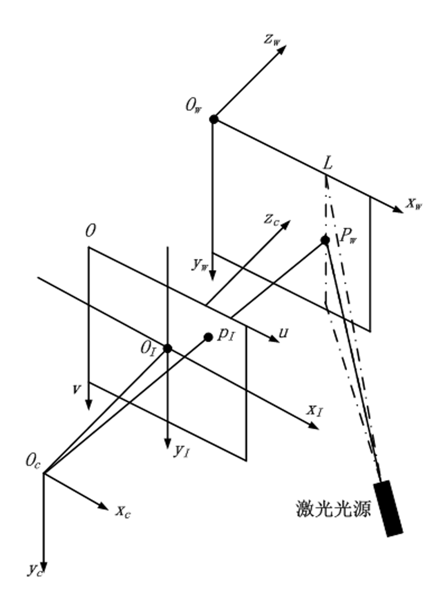
[0023] Such as figure 1 As shown, the camera 3D vision measurement model is usually based on the pinhole model. The world coordinate system is consistent with the sensor light plane coordinate system, set to O w -x w the y w z w , its O w -x w the y w coincides with the light plane. The image plane coordinate system is O I -X I Y I , where O I is the intersection of the optical axis and the image plane, and is the optical center of the image plane. o I and O c The distance f between them is the effective focal length of the objective lens imaging. where O I x I axis along the pixel lateral direction, O I Y I axis perpendicular to O I x I axis. In computer graphics, the point in the upper left corner is usually used as the origin of the image coordinates, that is, figure 1 The point O in is the origin to establish the image coordinate system Ouv. Computer Image Coordinate System Ouv and O I -X I Y I Coplanar, Ouv is O I -X I Y I along O I O obtaine...


PUM


Abstract

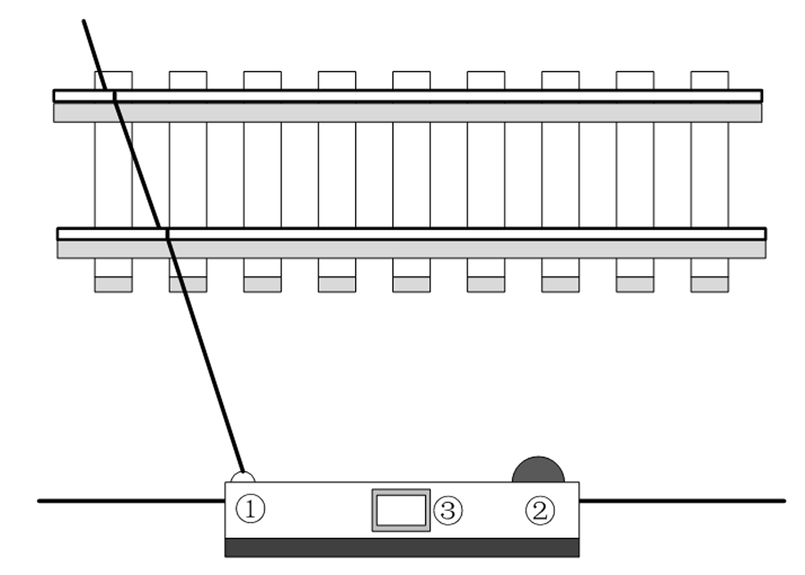
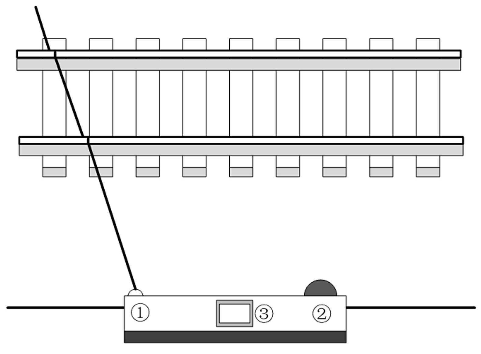
The invention relates to a measuring method for a non-contact steel rail sagging surface. In the method, a linear structure laser is adopted to emit laser rays to scan steel rails; images irradiated by the laser rays are collected by a camera; the images are processed by a microprocessor to obtain three-dimensional space coordinates of crossing points of the laser rays and the steel rails; a coordinate equation of the two steel rails and the steel rail surfaces can be obtained by carrying out fitting on the three-dimensional space coordinates of different crossing points, and thereby, the coordinate equation of the steel rail sagging surface is obtained; the linear structure laser (1) is controlled by the microprocessor (3) to emit the laser rays to irradiate the steel rails; the collected images are sent to the microprocessor (3) by the camera (2) for processing; and the coordinate equation of the steel rail sagging surface is worked out according to the transformational relation between the two-dimensional coordinate system under a computer image coordinate system and the three-dimensional space coordinates under a world coordinate system.

Description

technical field [0001] The invention relates to a method for measuring vertical surfaces of steel rails based on structured light three-dimensional visual detection technology, and belongs to the technical field of automatic detection. Background technique [0002] In recent years, the speed of domestic railways has been increased many times, especially the operation of high-speed EMUs, and the speed of trains is getting faster and faster, which also puts forward higher requirements for railway safety. When the platform, wires or other objects invade the space where the train runs, it will cause serious safety accidents. Therefore, the measurement of railway encroachment is extremely important. [0003] The method used by the railway department to measure the overrun of the freight car is mainly the relatively primitive human measurement, which requires the surveyor to climb to the top of the freight car and use tools such as a heavy hammer and a tape measure to measure. T...

Claims


Application Information

Patent Timeline
Patent Type & Authority Applications(China)
IPC IPC(8): B61K9/08G01C11/00
Inventor 张益昕王顺俞乾张旭苹李建华
Owner NANJING UNIV
Learn More