Hollow axis pneumatic mouth-tightening/ waist-suppressing machine
A technology of waist tightening machine and hollow shaft, which is applied to detonators, attack equipment and other directions, can solve the problems of low tightening precision, small tightening force and high failure rate of detonators, and achieves simple structure, high tightening force and failure rate. low effect
- Summary
- Abstract
- Description
- Claims
- Application Information
AI Technical Summary
Problems solved by technology
Method used
Image
Examples
Embodiment 1
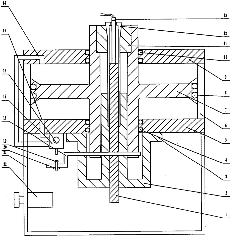
[0018] like figure 1 As described above, the hollow shaft pneumatic mouth tightening / waist tightening machine provided in this embodiment includes an outer cylinder 6, a base 21, a hollow piston shaft 7, an upper flange 9, a lower flange 5, an air control valve 17, and The chuck 12 for clamping the workpiece, the tapered sleeve 11 for cooperating with the chuck 12, the fixed seat 2, the position control contact piece 18, the outer barrel body 6 is arranged on the base 21,
[0019] The hollow piston shaft 7, the upper flange 9, the lower flange 5, and the outer barrel body 6 form a hollow shaft cylinder, and the hollow piston shaft 7 is in contact with the outer cylinder body through the sealing ring 4, the sealing ring 8, and the sealing ring 10. An air chamber is formed between the upper flange 9 and the hollow piston shaft 7, the hollow piston shaft 7 and the lower flange 5,
[0020] The fixed seat 2 is connected under the lower flange 5, the tapered end of the chuck 12 ext...
Embodiment 2
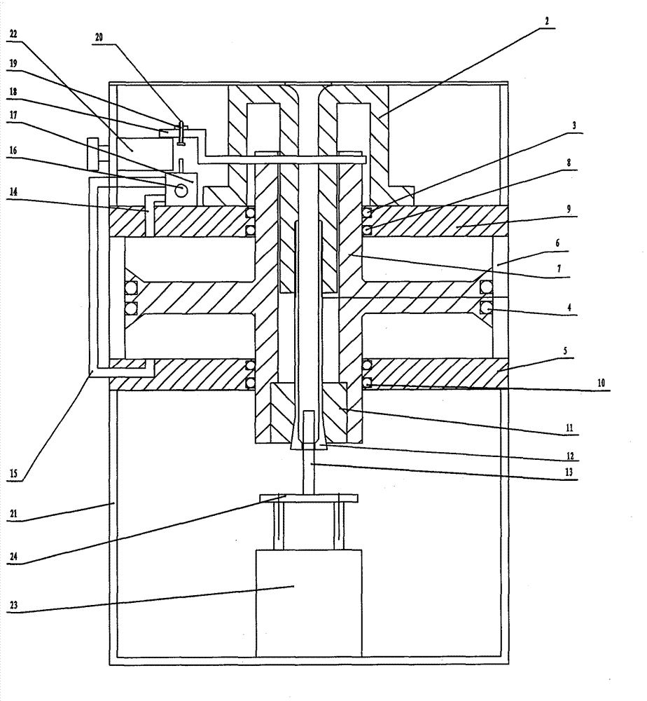
[0026] like figure 2 As described above, the hollow shaft pneumatic mouth tightening / waist tightening machine provided in this embodiment includes an outer cylinder 6, a base 21, a hollow piston shaft 7, an upper flange 9, a lower flange 5, an air control valve 17, and The chuck 12 for clamping the workpiece, the tapered sleeve 11 for cooperating with the chuck 12, the fixed seat 2, the position control contact piece 18, the outer barrel body 6 is arranged on the base 21,
[0027] The hollow piston shaft 7, the upper flange 9, the lower flange 5, and the outer barrel body 6 form a hollow shaft cylinder, and the hollow piston shaft 7 is in contact with the outer cylinder body through the sealing ring 4, the sealing ring 8, and the sealing ring 10. An air chamber is formed between the upper flange 9 and the hollow piston shaft 7, the hollow piston shaft 7 and the lower flange 5,
[0028] The fixed seat 2 is connected to the upper flange 9, the tapered end of the chuck 12 exten...
PUM
 Abstract
Description
Claims
Application Information
 - R&D
- Intellectual Property
- Life Sciences
- Materials
- Tech Scout
- Unparalleled Data Quality
- Higher Quality Content
- 60% Fewer Hallucinations
Browse by: Latest US Patents, China's latest patents, Technical Efficacy Thesaurus, Application Domain, Technology Topic, Popular Technical Reports.
© 2025 PatSnap. All rights reserved.Legal|Privacy policy|Modern Slavery Act Transparency Statement|Sitemap|About US| Contact US: help@patsnap.com


