Spinning apparatus for producing low-torque ring-spun yarn

A ring spinning machine, low torque technology, applied in the field of fiber yarn spinning, can solve the problems of high cost, poor spinning effect, inconvenient manufacture and use, etc., and achieve low residual torque, good yarn quality, good The effect of the false twist effect

Inactive Publication Date: 2011-05-25
NINGBO DECHANG PRECISION TEXTILE MACHINERY
View PDF10 Cites 17 Cited by
  • Summary
  • Abstract
  • Description
  • Claims
  • Application Information

AI Technical Summary

Problems solved by technology

[0007] In order to obtain low-torque ring-spun yarn, it is necessary to improve the existing ring-spun spinning method and spinning device, and there have been many studies on this, trying to achieve the goal with the traditional method of reducing the residual torque of the yarn, such as the Chinese patent Document CN1453401A discloses a single-ply torque-free ring-spun yarn processing method and equipment, which proposes to obtain a torque-free yarn on a traditional ring spinning machine through the above-mentioned physical method of reducing the residual torque of the yarn, and the structure is improved. The main point is to install a false twist device and a yarn splitting device between the output roller pair and the yarn guide hook of the existing ring spinning device, but the structure of the spinning device such as the false twist device provided by it is very complicated, which is inconvenient to manufacture and Use; especially the up and down movement of the yarn guide hook on the ring spinning machine will cause the change of the yarn guide angle a, and the set false twist device also needs to follow the up and down movement of the yarn guide hook, which not only makes the whole spinning device very It is complicated, and the yarn cannot get stable false twist effect, the spinning effect is poor, the cost is high, and it is not suitable for the actual needs of the existing industrial production ring spinning machine

Method used


Image

  • Spinning apparatus for producing low-torque ring-spun yarn
  • Spinning apparatus for producing low-torque ring-spun yarn
  • Spinning apparatus for producing low-torque ring-spun yarn

Examples


Embodiment Construction

[0029] The present invention will be further described in detail below in conjunction with the accompanying drawings and embodiments.

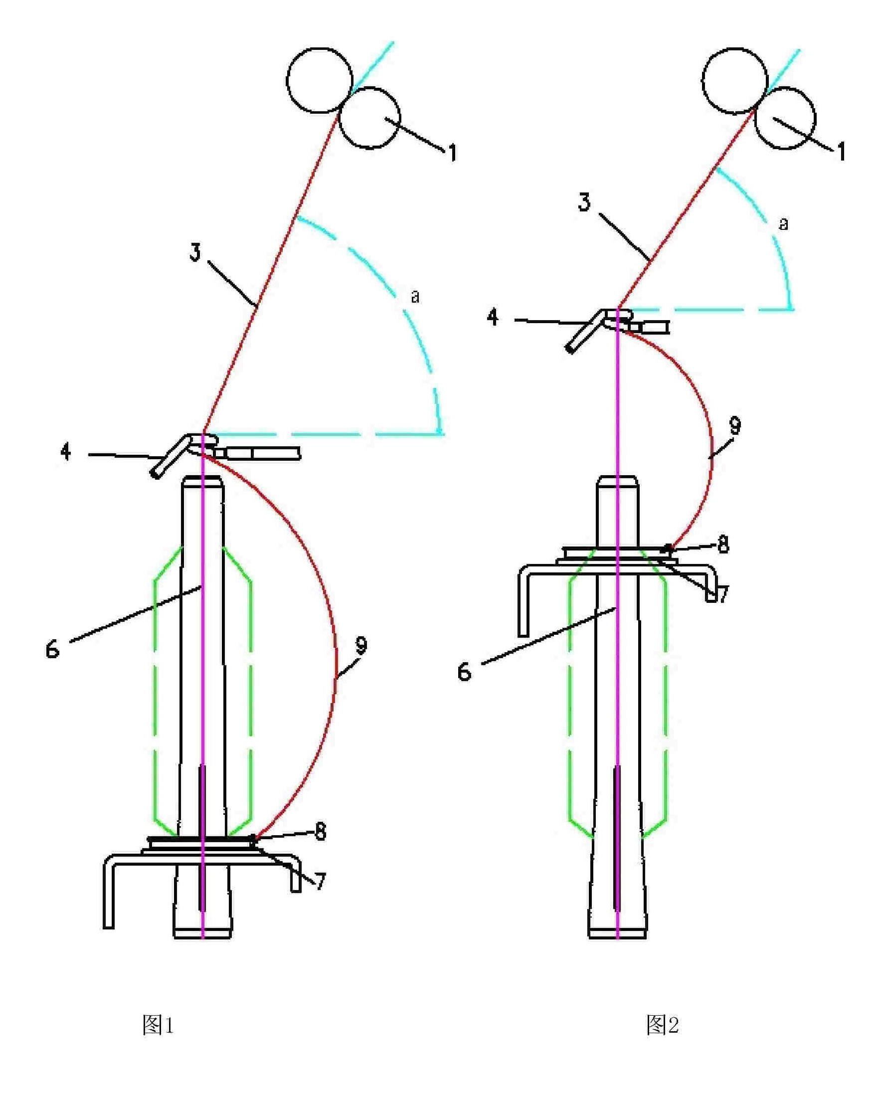
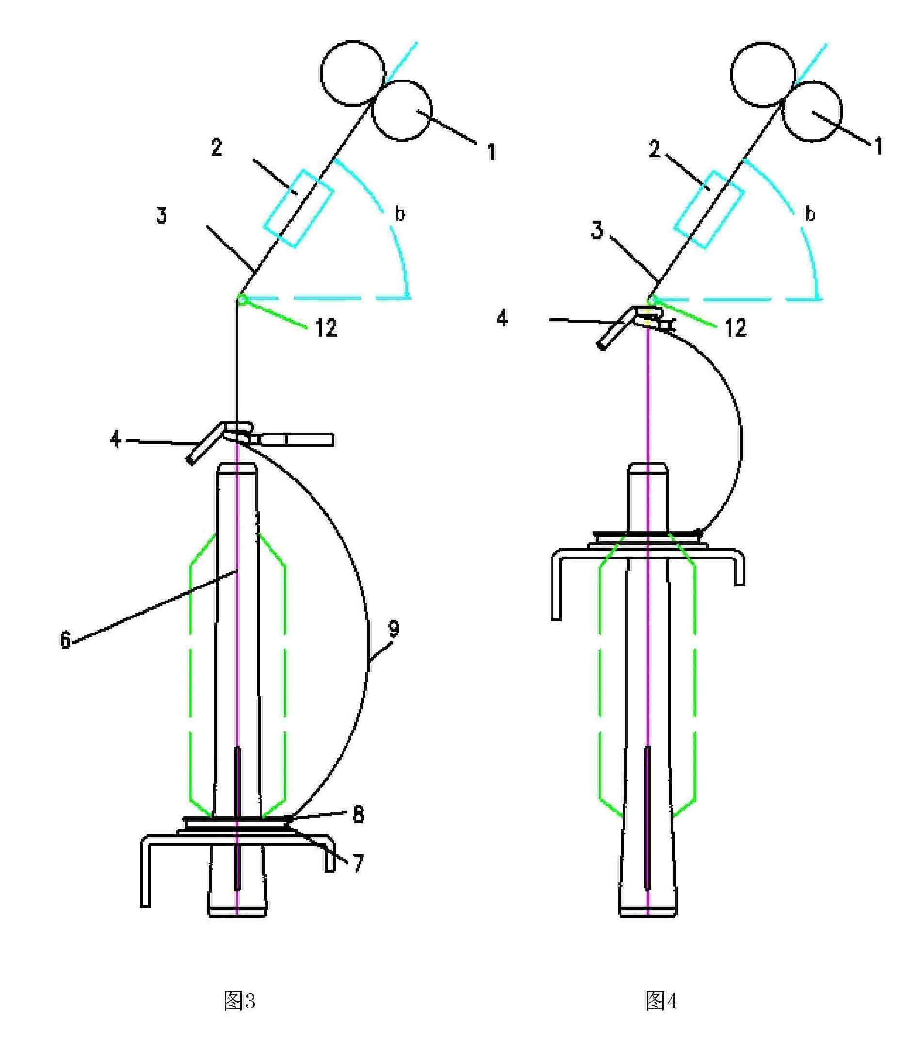
[0030] like image 3 , Figure 4 Shown, a kind of spinning device of producing low-torque ring-spun yarn, it comprises existing ring-spinning machine (referring to figure 1 and figure 2 ) and false twist device 2.

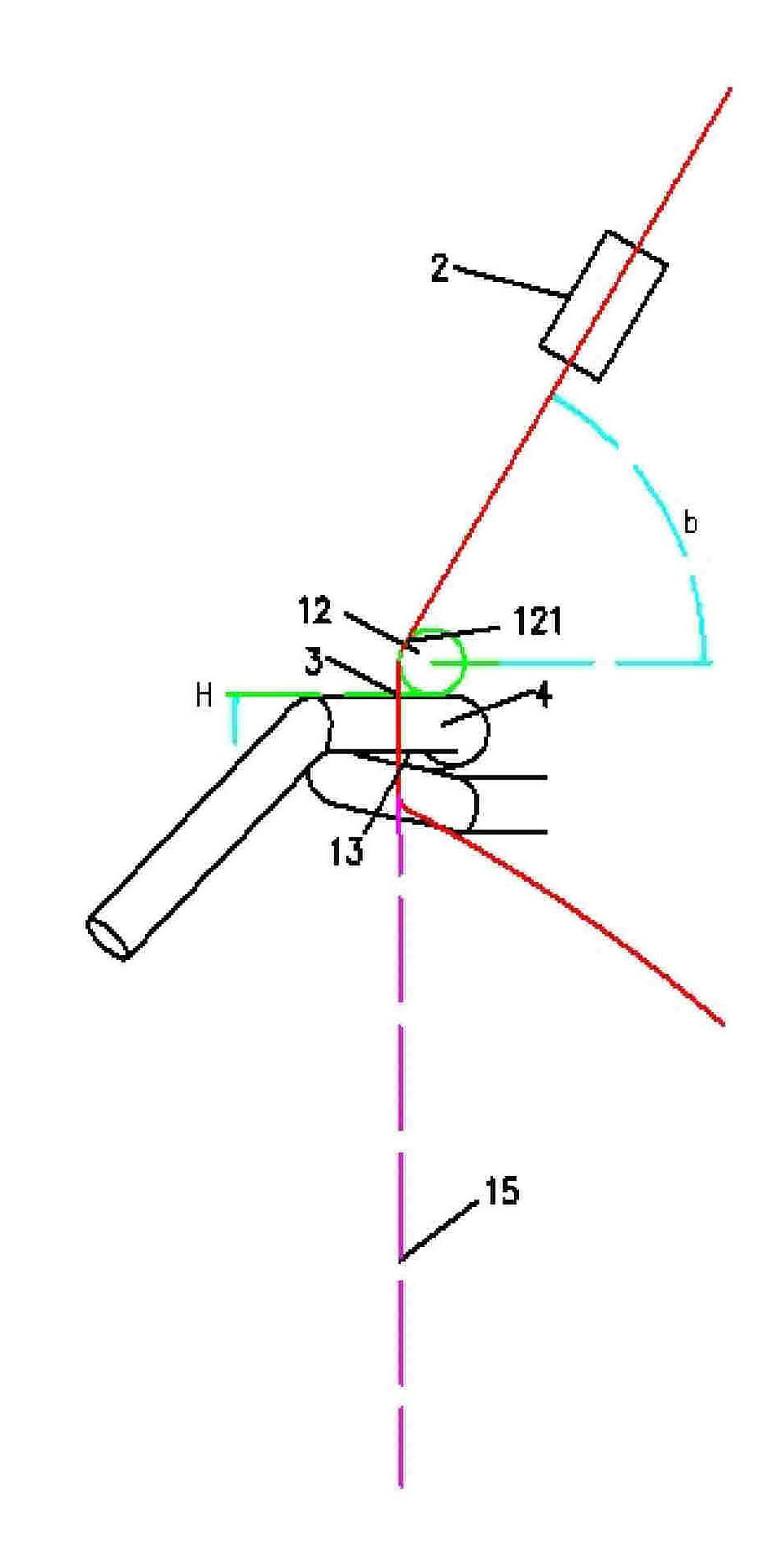
[0031] A yarn orientation device is arranged between the false twist device 2 and the guide hook 4, and the yarn orientation device includes an orientation wheel 12, and the yarn 3 is attached to the arc 121 on one side of the orientation wheel 12, see Figure 5 .

[0032] Above-mentioned directional wheel 12 can be connected on the fixing piece, and fixing piece is fixed to the frame of ring spinning machine or other places of machine by hinge again, also can be fixed on the suitable position of spinning machine periphery. The effect of the hinge is the same as that of the yarn guide hook (not shown), mainly for the convenie...


PUM


Abstract

The present invention provides a spinning apparatus for producing low-torque ring-spun yarns, wherein the apparatus comprises a ring spinner and a false-twist device; the false-twist device is arranged between a pair of output rollers of the ring spinner and a yarn guiding ditch, and a yarn orienting device is installed between the false-twist device and the yarn guiding ditch; the yarn orienting device comprises an orientation member, wherein the upper portion of the orientation member is provided with a yarn supporting curved surface, and yarns are leaned against the yarn supporting curved surface of the orientation member. The present invention is advantageous in that the structure of the spinning apparatus is simple, the existing ring spinner can be conveniently reconstructed with low cost, and the qualities of the produced yarns are good. The spinning apparatus provided by the invention can be applied to the solospun, siro spining, Sirofil spining and compact spinning devices for ring spining or combinations of the devices.

Description

technical field [0001] The invention belongs to the field of fiber yarn spinning, in particular to a low-torque ring-spun yarn spinning device, which enables the spun yarn to maintain a stable low torque. Background technique [0002] Existing twisting is an important part of short fiber spinning. During twisting, the yarn will generate a large amount of residual torque, which will have a great influence on the quality of subsequent products. For example, in knitted fabrics, due to the change in the internal torsional stress of the yarn, the loops of the fabric will rotate and release the internal torsional stress. As a result, one end of it will lift and protrude from the surface of the fabric, while the other end will stay inside the fabric. This deformation of the loops will increase the curvature of the fabric and produce a deformation like rib effect which is much to be avoided. [0003] At present, there are two main methods to reduce the residual torque of yarn: per...

Claims


Application Information

Patent Timeline
Patent Type & Authority Applications(China)
IPC IPC(8): D01H1/02D01H1/11D01H1/40
Inventor 竺韵德王卫徐时平周小平方扬邬建明
Owner NINGBO DECHANG PRECISION TEXTILE MACHINERY
Why Eureka
Try Eureka