Sling replacement method for suspension bridge

A technology for suspension bridges and slings, applied in the field of replacement of slings for suspension bridges, can solve problems such as the lack of mature cable replacement methods, and achieve the effect of convenient construction

Active Publication Date: 2011-05-25
JIANGSU FASTEN STEEL CABLE CO LTD +1
View PDF9 Cites 32 Cited by
  • Summary
  • Abstract
  • Description
  • Claims
  • Application Information

AI Technical Summary

Problems solved by technology

However, there is no mature

Method used


Image

  • Sling replacement method for suspension bridge
  • Sling replacement method for suspension bridge
  • Sling replacement method for suspension bridge

Examples


Embodiment Construction

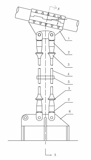
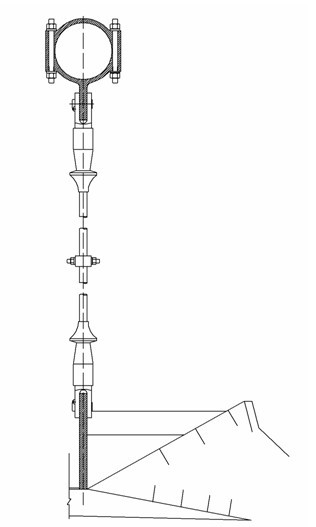
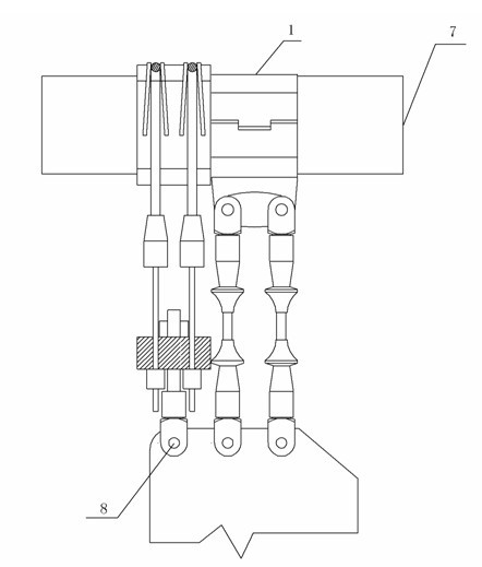
[0026] see image 3 and Figure 4 , image 3 It is a schematic diagram of the implementation process of the present invention. Figure 4 It is a schematic diagram of the temporary cable clip involved in the present invention. The suspension bridge suspension cable that the present invention relates to changes cable method, and described method comprises following process:

[0027] 1) Install a temporary cable clamp 9 on the main cable 7 of the suspension bridge, and pad the rubber plate inside the temporary cable clamp to prevent the temporary cable clamp from damaging the protective layer of the main cable.

[0028] 2) Two auxiliary cables 10 are erected on the temporary cable clamp, and the middle of the two auxiliary cables bypasses the groove of the temporary cable clamp, and four small pull rods 11 are connected at both ends, and the auxiliary cables are temporarily fixed with fasteners to prevent slippage.

[0029] 3) Install the tie rod 15 on the hoisting hole of th...


PUM


Abstract

The invention relates to a sling replacement method for a suspension bridge, which comprises the following steps of: arranging a temporary cable clamp on a main cable of the suspension bridge; erecting auxiliary slings on the temporary cable clamp; arranging a main pull rod on an erection hole, screwing a nut on the end part of the main pull rod, inserting small pull rods into four hole positions on the two sides of a base plate, and arranging bolt pullers or jacks on the end parts of the small pull rods; starting the tensioning of the bolt pullers or the jacks, continuously knocking a pin shaft in a lower lug of an old sling until the pin shaft is knocked out, and screwing the nut on the main pull rod; lifting the original sling, knocking the pin shaft out of an upper lug of the old sling, taking the original sling down, and arranging a new sling by using the method contrary to the method for dismantling the old sling; after the new sling is arranged, unscrewing the nuts on the bolt pullers or jacks, releasing pressure, unscrewing the nut on the main pull rod, and repeating the operations until the new sling is completely tensioned; and dismantling the auxiliary slings, the base plate, the main pull rod, the small pull rods and the temporary cable clamp. The sling replacement method for the suspension bridge is convenient to construct, safe and reliable.

Description

technical field [0001] The invention relates to a method for replacing slings of a suspension bridge, which belongs to the technical field of bridge construction engineering. Background technique [0002] Suspension bridges usually consist of four parts: cable system (including main cables and suspension cables), bridge towers, stiffening beams and anchorages. Its installation structure is as figure 1 and figure 2 shown. The stiffening girder transmits the load of the bridge deck to the main cable through the sling, and the main cable acts on the load on the bridge tower and anchorage. Therefore, the suspension cable is the main force transmission component of the suspension bridge. Since the design life of the suspension bridge is generally 100 to 200 years, and the sling, as a replaceable component, generally has a life span of 30 to 50 years. The slings need to be replaced for the longevity of the overall structure. But there is no mature method of changing the rop...

Claims


Application Information

Patent Timeline
IPC IPC(8): E01D22/00E01D19/16
Inventor 宁世伟赵军徐文磊薛花娟周祝兵姚永峰吴琼赵成哲
Owner JIANGSU FASTEN STEEL CABLE CO LTD
Why Eureka
Try Eureka