Floating ball type one-way drainage valve on slope or retaining wall

A technology of retaining wall and floating ball, applied in the direction of control valves, valve devices, artificial waterways, etc., can solve the problems of inflexible use, drainage failure, water loss, etc., achieve low cost, reduce external water pressure, prevent The effect of strong permeability

Inactive Publication Date: 2012-03-28
南通市通州区生产力促进中心
View PDF0 Cites 0 Cited by
  • Summary
  • Abstract
  • Description
  • Claims
  • Application Information

AI Technical Summary

Problems solved by technology

In order to discharge groundwater in time, it is generally necessary to install an appropriate number of drainage pipes in slope protection and retaining walls. However, when the water level in channels, rivers, and spillways is higher than the groundwater level, water will leak out through the drainage pipes, resulting in water loss. , this contradiction between seepage control and drainage has not been effectively resolved for a long time
In some important long-distance water transmission channels, a backstop water collection tank is installed on the drain pipe, but because the flap door that acts as a backstop can only be closed when the water pressure difference is large, the use is not flexible enough, and the mud Sand is easy to silt up in the water collection tank and cause drainage failure

Method used


Image

  • Floating ball type one-way drainage valve on slope or retaining wall
  • Floating ball type one-way drainage valve on slope or retaining wall
  • Floating ball type one-way drainage valve on slope or retaining wall

Examples


Embodiment

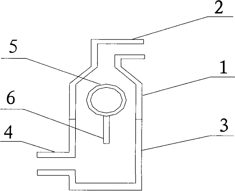
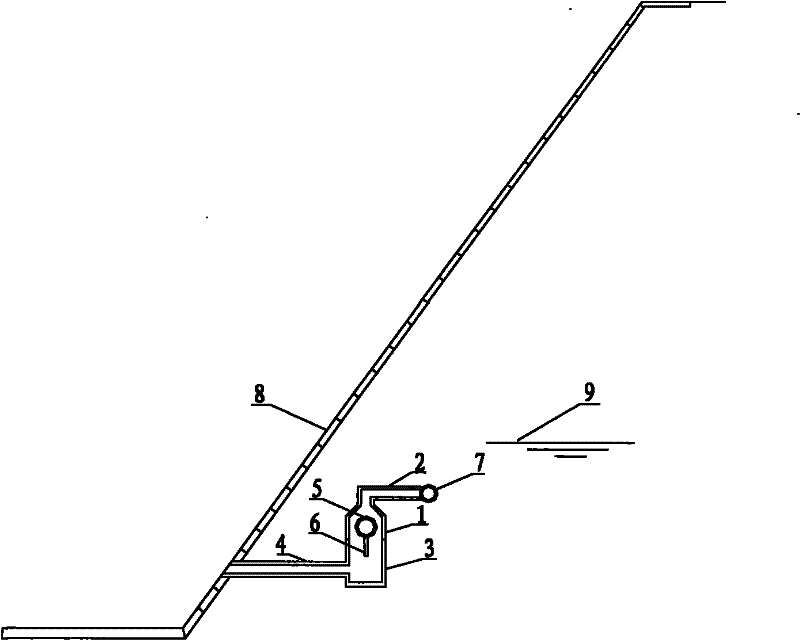
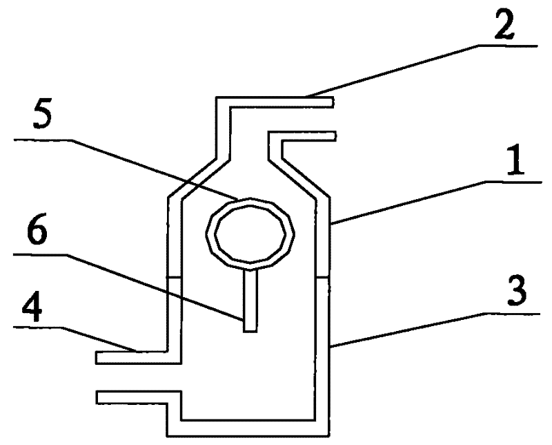
[0011] Such as figure 1 As shown, the present invention is a floating ball type one-way drain valve on a slope and retaining wall, which includes an upper valve body 1 and an outlet pipe 2 connected to the valve body 1, a lower valve body 3 and a valve body 3 The connected outlet pipe 4, the floating ball 5 and the straight rod 6 connected with the floating ball 5, the above structures are all made of hard polyvinyl chloride material. The upper valve body 1 is funnel-shaped, the neck of the upper valve body 1 is a smooth rotating surface, the lower valve body 3 is barrel-shaped, and the floating ball is a hollow ball. The upper valve body 1 and the lower valve body 3 have the same diameter, and the two are screwed together to form a valve body. The floating ball 5 can move up and down in the valve body under the action of buoyancy, and drives the straight rod 6 to disturb the water at the bottom of the valve body to prevent mud and sand from accumulating. The diameters of th...


PUM


Abstract

The invention relates to a floating ball type one-way drainage valve which is capable of preventing stored water leakage and discharging ground water in time and is applicable to a slope or a retaining wall of hydraulic engineering. The floating ball type one-way drainage valve consists of an upper valve body, a lower valve body, a floating ball and a drainage pipe, wherein the upper valve body has a funnel shape, a smooth camber neck part, and a top part connected with the drainage pipe, the lower valve body has a cylindrical shape and a bottom part connected with the drainage pipe, the floating ball is a hollow ball and has a straight bar attached onto the surface, and the upper valve body and the lower valve body are connected with each other through screws. The floating ball moves up and down in the valve body, and the straight bar stirs the sludgy on the bottom part of the valve body to prevent blockage. The upper and lower valve bodies share the same diameter, the diameter of the drainage pipe is smaller than that of the floating ball, and the sum of the length of the diameter of the floating ball and the length of the straight bar is greater than the inside diameter of the valve body. When the impounded level is higher than the ground water level, the floating ball moves up to block the drainage hole. When the impounded level is lower than the ground water level, the floating ball moves down and the ground water enters the valve body and is discharged through the drainage pipe. The floating ball type one-way drainage valve facilitates the stability of the slope and the retaining wall, and has a simple structure, high rigidity, high sensitivity and reliability, and is resistant to sludge and rust, low in cost and high in durability.

Description

technical field [0001] The invention relates to a floating ball type one-way drain valve on a side slope and a retaining wall, in particular to a water conservancy engineering side slope and a retaining wall that can effectively prevent water storage from seeping out and discharge groundwater in time. One-way drain valve. Background technique [0002] In water conservancy projects, in order to meet the requirements of anti-seepage, anti-erosion, and reduction of roughness, it is necessary to protect the slope or bank wall of channels, embankments, and spillways. The types of protection include concrete slab slope protection, mortar stone slope protection, Concrete retaining walls, masonry retaining walls, etc. In areas with a high groundwater level, groundwater is extremely unfavorable to the stability and safety of slope protection and retaining walls. In order to discharge groundwater in time, it is generally necessary to install an appropriate number of drainage pipes i...

Claims


Application Information

Patent Timeline
Patent Type & Authority Patents(China)
IPC IPC(8): F16K15/00E02B5/08
Inventor 韩伟韩艺浓
Owner 南通市通州区生产力促进中心
Why Eureka
Try Eureka