Pressurized water conveying tunnel gravity self-locking one-way water drainage reducing valve

A technology for water conveyance tunnels, drainage and pressure reduction, applied in the directions of hydroelectric power generation, hydroelectric power station, control valve, etc., can solve the problems of reducing the water pressure outside the lining, affecting the performance of engineering benefits, and increasing the leakage loss of water in the water conveyance tunnel. , to reduce the external water pressure and reduce the stress on the lining structure

Pending Publication Date: 2019-09-20
浙江省水利水电勘测设计院有限责任公司
View PDF0 Cites 0 Cited by
  • Summary
  • Abstract
  • Description
  • Claims
  • Application Information

AI Technical Summary

Problems solved by technology

[0004] The setting of drainage relief holes is beneficial to improve the quality of the lining construction period, but the drainage relief holes can only be reserved in the tunnel section where the external water pressure is greater than the internal water pressure. It must be sealed when the consolidation grouting is completed, otherwise the internal water seepage will increase the water leakage loss of the water delivery tunnel, which will affect the performance of the project. The effect of water pressure

Method used


Image

  • Pressurized water conveying tunnel gravity self-locking one-way water drainage reducing valve
  • Pressurized water conveying tunnel gravity self-locking one-way water drainage reducing valve
  • Pressurized water conveying tunnel gravity self-locking one-way water drainage reducing valve

Examples


Embodiment Construction

[0021] The present invention will be described in further detail below in conjunction with the accompanying drawings.

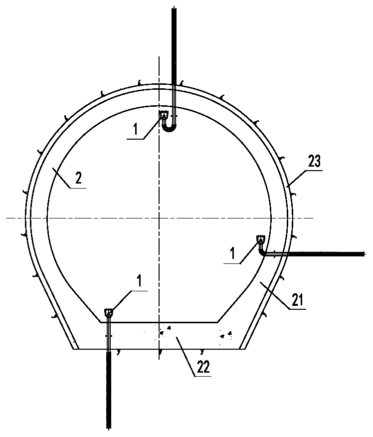
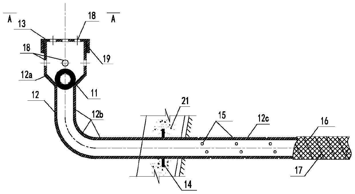
[0022] Such as Figure 1 to Figure 3 As shown, a gravity self-locking one-way drainage pressure reducing valve 1 of a pressurized water delivery tunnel according to the present invention is generally installed below the waist line of the side wall lining 21 of the pressurized water delivery tunnel 2 or on the floor lining 22. Drain relief hole arrangement, is made up of steel ball 11, sleeve pipe 12, valve cover 13.

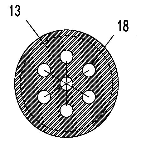
[0023] The sleeve 12 includes a container section 12a, a conduit section 12b and a flower tube section 12c. The container section 12a is located inside the pressurized water delivery tunnel 2, and a steel pipe with permeable holes 18 is provided for the pipe wall. The inner diameter of the steel pipe is larger than the diameter of the steel ball 11. Screw thread 19 is connected to valve cover 13; conduit section 12b is an impermeable stainless...


PUM


Abstract

The invention discloses a pressurized water conveying tunnel gravity self-locking one-way water drainage reducing valve comprising a steel ball, a sleeve and a valve cover. The sleeve comprises a container section, a guide pipe section and a flower pipe section, the container section is located inside a pressurized water conveying tunnel, the outer wall of a pipe opening at the upper portion of the container section is provided with a screw thread to be connected with the valve cover, and the bottom part of the container section is provided with a transition section to be connected with the guide pipe section; one end of the guide pipe section is connected to the container section, and the other end of the guide pipe section is connected with the flower pipe section; and the steel ball is arranged in the container section of the sleeve, and the outer diameter of the steel ball is larger than the inner diameter of the guide pipe section of the sleeve and smaller than the inner diameter of the container section of the sleeve. The pressurized water conveying tunnel gravity self-locking one-way water drainage reducing valve can overcome the contradiction that the pressurized water conveying tunnel needs to allow outer water internal drainage and needs to prevent internal water extravasation, can be arranged at the position of a drainage decompression hole during the construction period and conducts flow diversion to improve the tunnel lining pouring quality; relying on gravity self-locking, internal water extravasation can be prevented without blocking a drainage hole during the operation period; and when the tunnel is emptied and repaired, effective drainage can be carried out, the external water pressure can be effectively reduced, and the stress of a lining structure is reduced.

Description

technical field [0001] The invention relates to a pressure reducing valve device in a pressurized water delivery tunnel in a water conservancy and hydropower project, in particular to a pressurized water delivery tunnel project, which can drain water into the tunnel when the external water pressure of the tunnel lining is high, and the internal water pressure is high When using gravity self-locking valve one-way drainage relief valve device. Background technique [0002] In pressurized water tunnels, the stress of the tunnel lining structure is mainly determined by the working conditions of the external water pressure. Reducing the external water pressure is not only conducive to improving the stress of the lining structure, reducing the risk of lining cracking, and improving the durability of the tunnel lining structure. When lining is poured, setting drainage holes in the hole section with large leakage is also beneficial to improve the quality of lining pouring. [0003]...

Claims


Application Information

Patent Timeline
Patent Type & Authority Applications(China)
IPC IPC(8): F16K17/12F16K17/164F16K15/04F16K27/02F16L5/10E02B9/06
CPCE02B9/06F16K15/048F16K17/12F16K17/164F16K27/0209F16K27/0245F16L5/10Y02E10/20
Inventor 张永进李进赖勇杜强强
Owner 浙江省水利水电勘测设计院有限责任公司
Why Eureka
Try Eureka