Air intake apparatus for internal combustion engine

A technology for air intake devices and internal combustion engines, applied to internal combustion piston engines, combustion engines, combustion air/combustion-air treatment, etc., can solve the problems of increasing, hindering the output of internal combustion engines, reducing the mixing ratio of air filling rate, etc.

Inactive Publication Date: 2011-05-25
AISIN SEIKI KK
View PDF3 Cites 4 Cited by
  • Summary
  • Abstract
  • Description
  • Claims
  • Application Information

AI Technical Summary

Problems solved by technology

Therefore, the air filling rate and the mixing ratio of air and fuel tend to decrease, which hinders the increase of the output of the internal combustion engine

Method used


Image

  • Air intake apparatus for internal combustion engine
  • Air intake apparatus for internal combustion engine
  • Air intake apparatus for internal combustion engine

Examples


no. 1 example

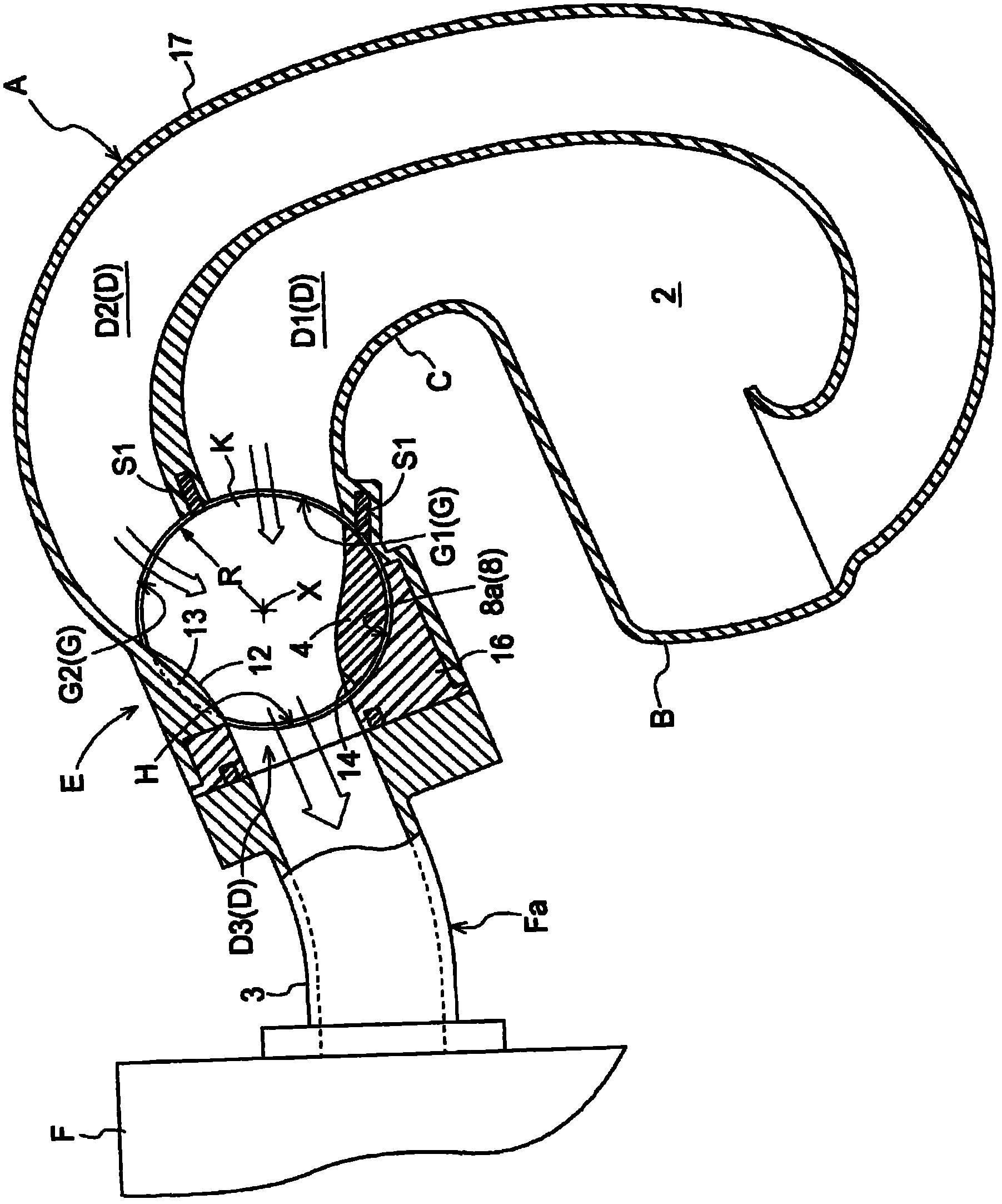
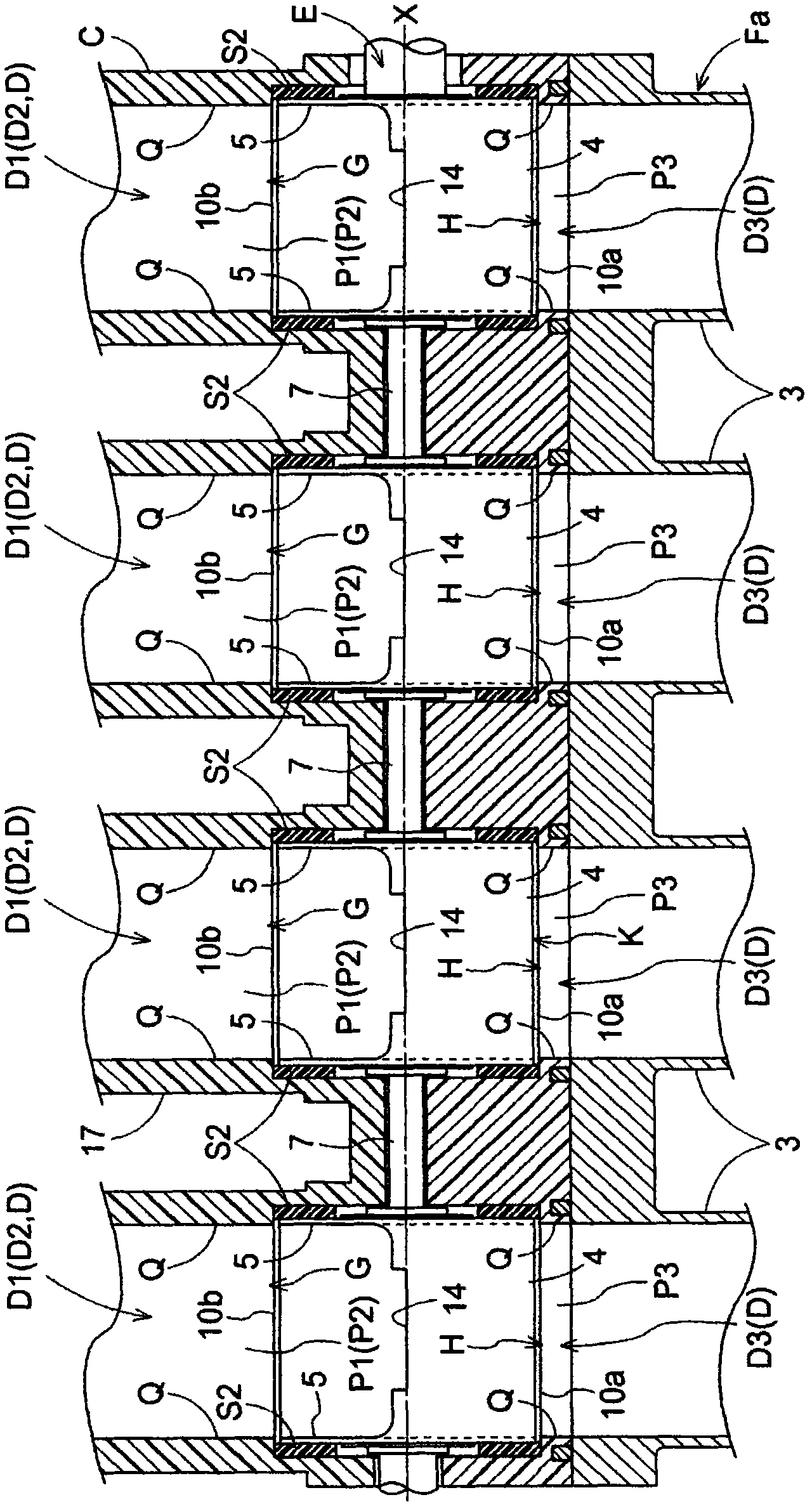
[0035] Next, a first embodiment will be described. Such as Figure 1 to Figure 3 As shown, an air intake device for an internal combustion engine (hereinafter simply referred to as an air intake device) A includes a buffer tank B, a housing C, and a rotary valve E. The buffer tank B includes an inlet 1 and an air storage cavity 2 . The housing C having a hollow shape includes an air inlet D, an air inlet G, and an air outlet H. As shown in FIG. The rotary valve E is installed at the housing C.

[0036] The buffer tank B and the case C are integrally formed by joining resin molded products. The throttle valve is connected to the inlet 1 of the buffer tank B, so that the outside air whose air flow is adjusted by the throttle valve is sucked into the air storage cavity 2 through the inlet 1 .

[0037] The intake port D is connected to the intake portion Fa of each of the four cylinders of the engine F (as an internal combustion engine). That is, according to the present embo...

no. 2 example

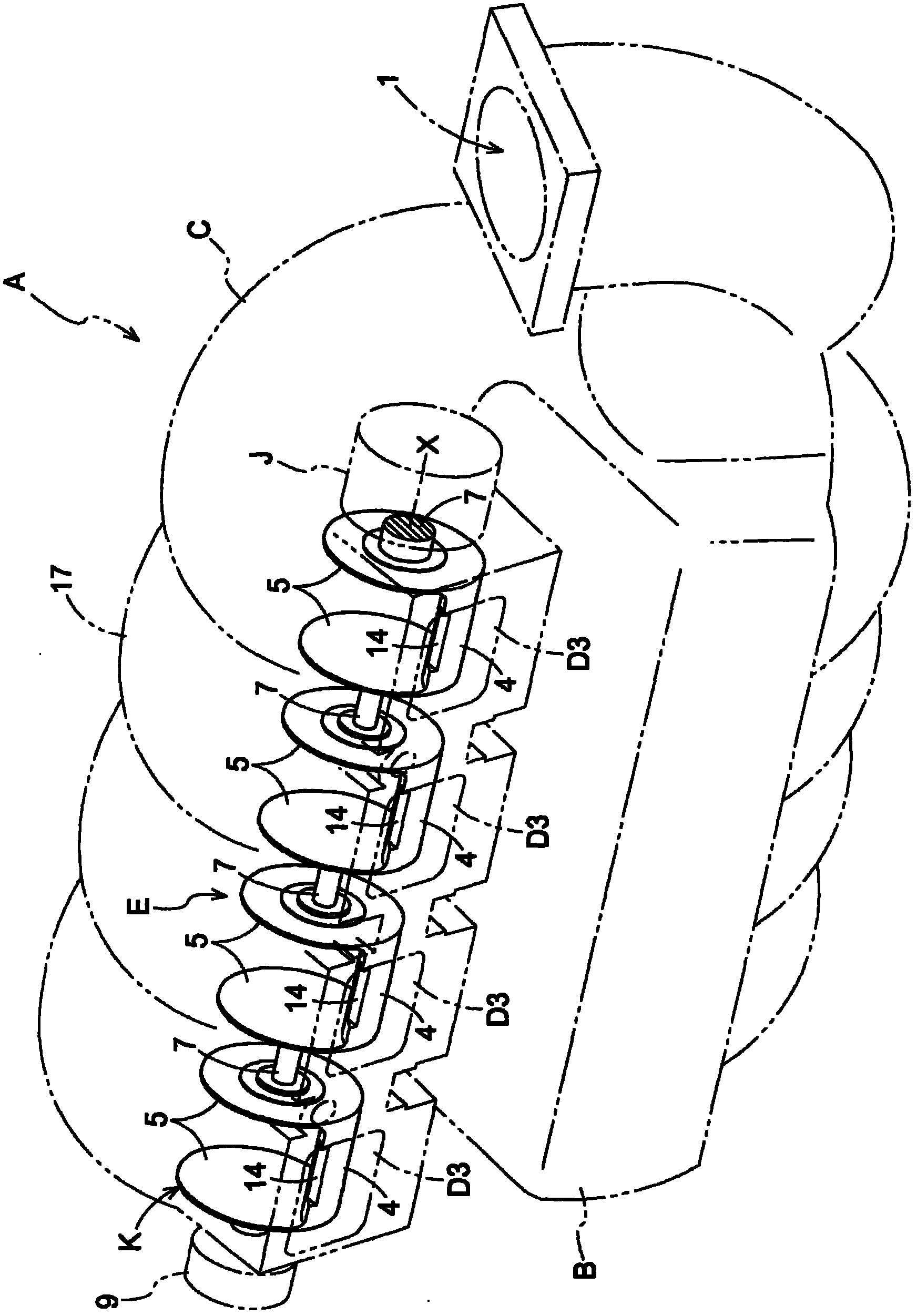
[0062] Below, refer to Figure 12A with Figure 12B A second embodiment will be described. In the second embodiment, the case C is constituted by a body portion 17 and a cover member 16 provided with each air outlet H. As shown in FIG. An insertion port 15 is formed at the body portion 17 , and the rotary valve E is inserted into the insertion port 15 in a direction perpendicular to the rotation axis X and mounted. According to the second embodiment, each inner surface forming portion 13 is provided at the cover member 16 instead of the body portion 17 so that the inner peripheral surface 12 is formed.

[0063] Accordingly, if Figure 12A As shown, in the case of installing the rotary valve E to the main body 17 , the rotary valve E is inserted into the insertion port 15 in a direction perpendicular to the rotation axis X, and installed inside the main body 17 . Then, if Figure 12B As shown, when the insertion opening 15 is covered with the cover member 16, each inner su...


PUM


Abstract

An air intake apparatus for an internal combustion engine includes a casing (C) including an intake port (G) and a discharge port (H), a rotary valve (E) rotatable around a rotational axis (X) within the casing (C) and including a valve element (4) that controls a connecting state between the intake port (G) and the discharge port (H), and an inner surface forming portion (13) formed at an inner surface (12) of the casing (C) along the rotational axis (X) of the rotary valve (E) and defined from the intake port (G) to the discharge port (H), a distance of the inner surface (12) from the rotational axis (X) being shorter than a maximum rotational radius (R) of the valve element (4).

Description

technical field [0001] The invention relates to an air intake device for an internal combustion engine. More specifically, the present invention relates to such an air intake device for an internal combustion engine, which includes a housing having an air inlet and an air outlet, and a rotary valve having a valve body rotatable around a rotation axis inside the housing and controlling Connection status between gas port and gas outlet. Background technique [0002] According to the known air intake device for an internal combustion engine, the inner surface of the casing formed around the rotation axis of the valve body, that is, the inner surface surrounding the rotation area of ​​the valve body in a direction perpendicular to the rotation axis of the valve body, is formed in a cylindrical shape, and is aligned with the valve body. The axes of rotation are coaxial. An air inlet and an air outlet are formed in openings on different parts of the inner surface of the valve bo...

Claims


Application Information

Patent Timeline
Patent Type & Authority Applications(China)
IPC IPC(8): F02M35/104F02D9/10
CPCF02D9/16F02B27/0284Y02T10/146F02B27/0215F02M35/10039F02M35/10065F02B27/0263Y02T10/14Y02T10/12
Inventor 坂上英二
Owner AISIN SEIKI KK
Why Eureka
Try Eureka