Combined type sealing device with double end faces
A sealing device and combined technology, applied in the direction of engine sealing, engine components, mechanical equipment, etc., can solve the problems of loss of working ability of the seal, difficult to improve the service life, failure of the plane seal, etc., to achieve high working reliability, internal The effect of small temperature difference outside and stable sealing performance
- Summary
- Abstract
- Description
- Claims
- Application Information
AI Technical Summary
Problems solved by technology
Method used
Image

Examples
Embodiment 1
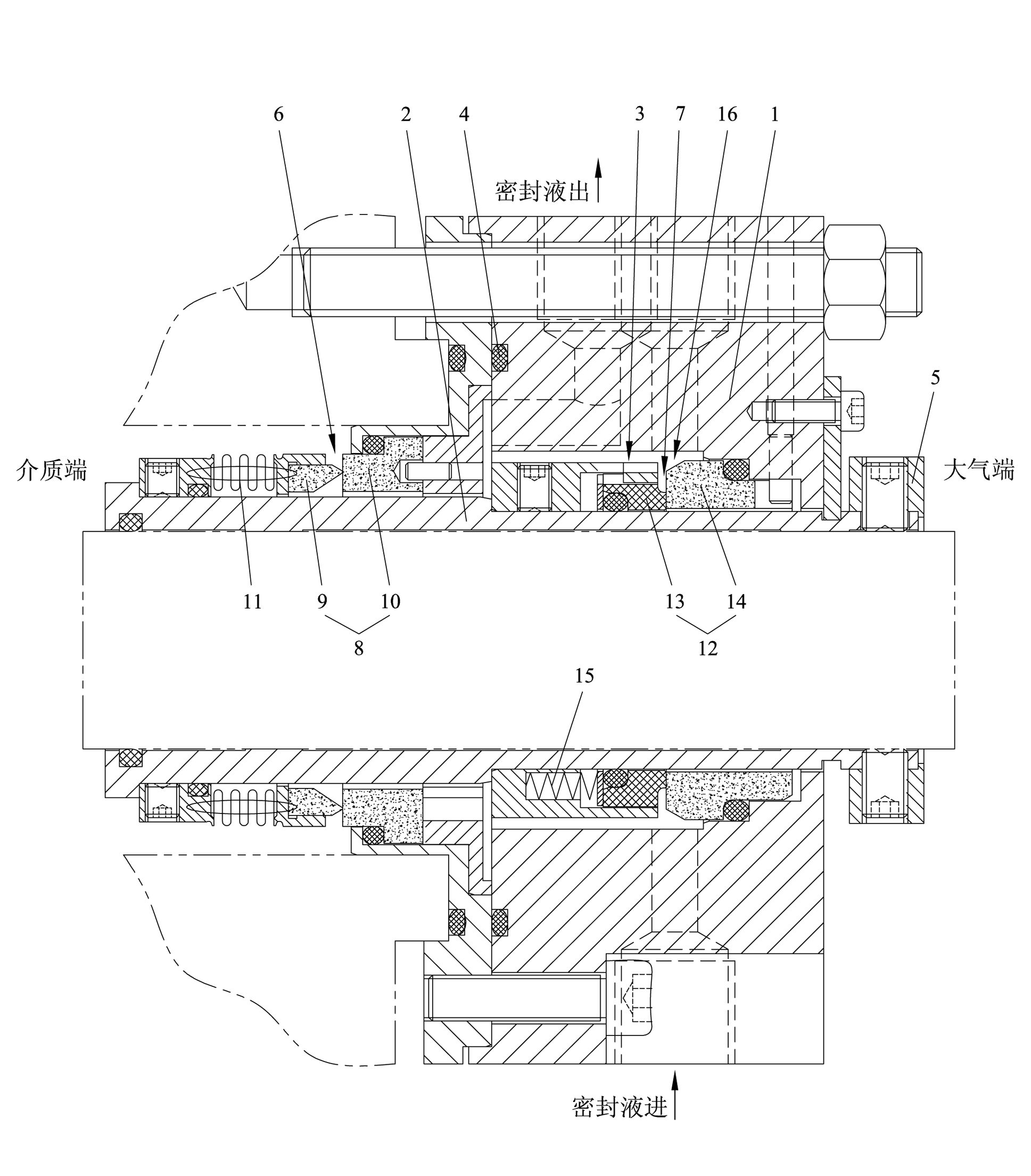
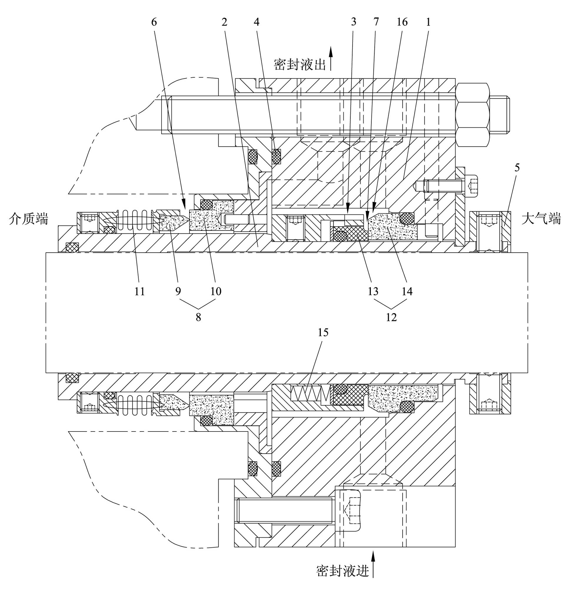
[0021] Embodiment one: see attached figure 1 shown.
[0022] A double-face combined sealing device, installed in fluid conveying equipment, used to achieve shaft end sealing, including gland 1, shaft sleeve 2, driving ring 3, sealing ring 4, limit block 5, main seal 6, and auxiliary seal 7.
[0023] The main seal is in direct contact with the sealed fluid, and the secondary seal is in direct contact with the atmosphere.
[0024] The main seal 6 is a knife-edge seal, and the main seal 6 includes a pair of main friction rings 8 . The main friction ring 8 includes a driving ring 9 and a main static ring 10. The surface of any one main friction ring 8 that is in contact with another main friction ring 8 is its friction surface, and the friction surface is annular. The single friction surface of the driving ring 9 The side width is smaller than the unilateral width of the friction surface of the main static ring 10, and the unilateral width of the friction surface of th...
PUM
| Property | Measurement | Unit |
|---|---|---|
| Unilateral width | aaaaa | aaaaa |
Abstract
Description
Claims
Application Information