LED lamp

A technology of LED lamp tube and tube body, which is applied to the cooling/heating device of lighting device, lighting and heating equipment, semiconductor device of light-emitting element, etc. Manufacturing cost and other issues, to achieve the effect of large illumination angle, ideal heat dissipation effect, and low cost

Inactive Publication Date: 2011-05-25
ZHONGSHAN WEIQIANG TECH
View PDF5 Cites 14 Cited by
  • Summary
  • Abstract
  • Description
  • Claims
  • Application Information

AI Technical Summary

Problems solved by technology

Since the lamp tube is installed horizontally between two lamp holders, the two ends of the tube body are fixedly supported by the lamp holder, while the middle part is affected by its own weight and has a downward stress. For the first type of LED lamp tube, the plastic tube body It will soften when heated, and the middle part will be slightly deformed due to the influence of gravity. Therefore, after a long-term use of the lamp tube, it will obviously become a shape of downward bending in the middle part, which affects the appearance of the lamp tube and is unsafe to use; while the second Although the back of this kind of tube body is made of aluminum profiles, although it has a good heat dissipation effect and is not easy to deform when heated, the aluminum material will greatly increase the manufacturing cost, resulting in expensive products and lack of competitiveness in the market. The aluminum profile is used to fix the circuit board, which will make the position of the circuit board in the tube body closer to the front of the tube, thus reducing the irradiation angle of the lamp tube and reducing the lighting effect

Method used


Image

  • LED lamp
  • LED lamp
  • LED lamp

Examples


Embodiment Construction

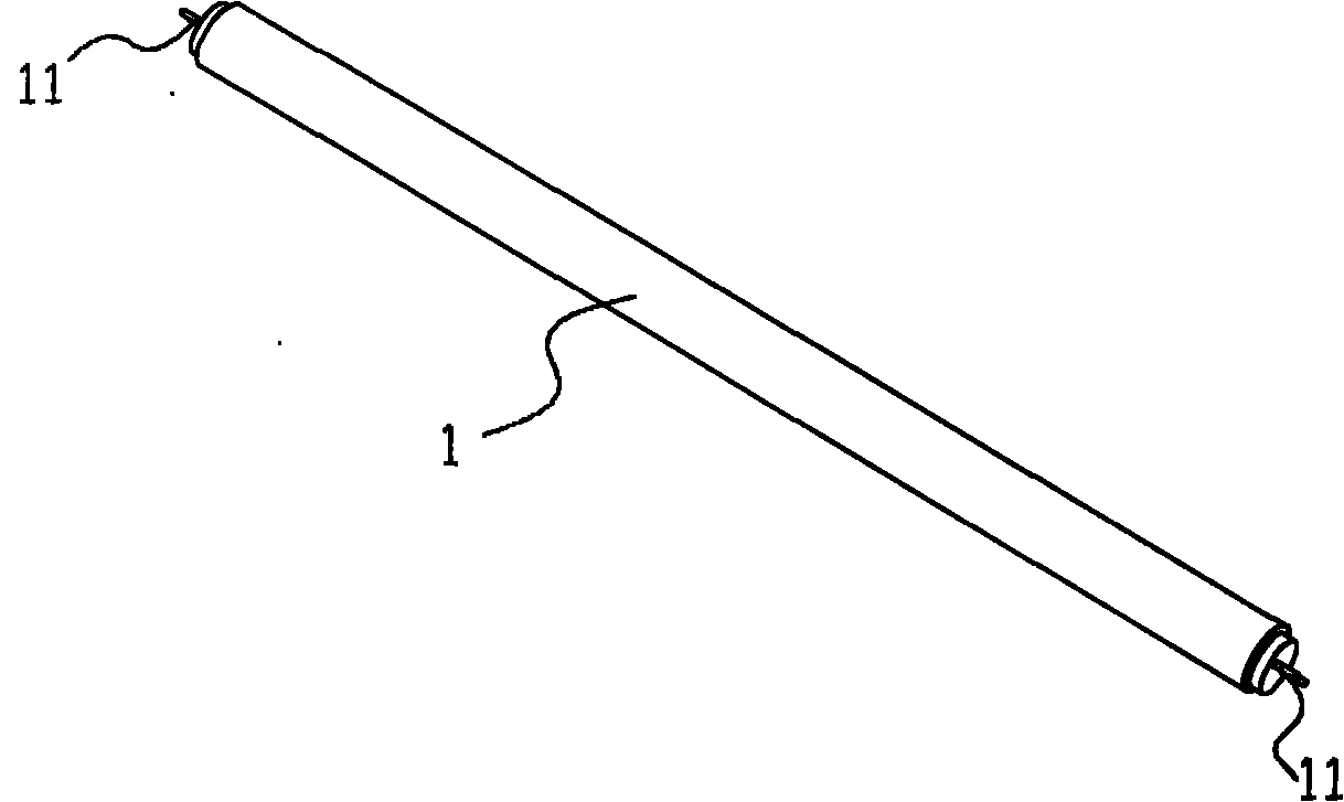
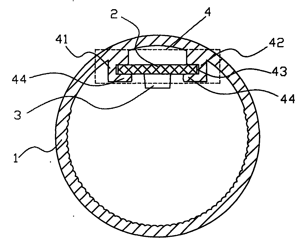
[0041] Such as figure 1 and figure 2 As shown, an LED lamp tube provided by the present invention includes a tube body 1, a circuit board 2 with a rectification unit is installed in the tube body 1, a light-emitting diode module 3 is arranged on the circuit board 2, and the two ends of the tube body 1 An electrical plug group 11 is provided, wherein the circuit board 2 is connected to the electrical plug group 11, and the electrical plug group 11 can be plugged into a conventional fluorescent lamp socket to connect to an external power source to obtain electricity.

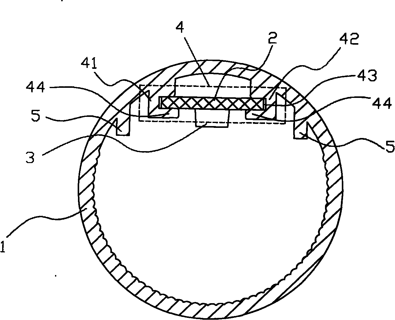
[0042] refer to figure 2 , the tube body 1 is integrally formed into a tube, which is generally a round tube or an elliptical tube. There are integrally formed wave stripes on the inner side wall of the tube body 1, so that it has a lens function to expand the light-emitting angle; as figure 2 In the shown embodiment one, a set of supporting and positioning ribs 4 is provided on the inner side of the back of ...


PUM


Abstract

The invention discloses an LED lamp which comprises a lamp body, wherein a circuit board with a rectifier element is installed in the lamp body and is provided with an LED module group, and electric insertion groups are arranged at both ends of the lamp body. The LED lamp is characterized in that the lamp body is an integrally formed tube, at least one group of support locating ribs is arranged at the inner side of the back part of the lamp body, every two support locating ribs are integrally formed on the inner wall of the lamp body and extend along the axial direction, the circuit board is in a long strip shape, at least one group of the LED module groups is fixed on the positive surface of the circuit board, and two ribs of the support locating ribs are clamped and fixed to both sides of the circuit board. The LED lamp adopts the integrally formed lamp body, the lamp body is internally provided with support locating ribs, the lamp body is made of plastic materials so that the LED lamp has low cost and the lamp body has enough strength and firm and reliable structure, is difficult to deform in a state of heating by working of the LED lamp and also has better light emitting effect.

Description

technical field [0001] The invention relates to an LED lamp, in particular to an LED lamp tube. Background technique [0002] Fluorescent lamps are commonly used lighting fixtures. Traditional fluorescent lamps are filled with fluorescent powder, which contains a variety of toxic heavy metals, which are very harmful to the human body and the ecological environment during manufacture and use. In addition, fluorescent lamps consume a lot of power and have a short service life. It often cannot meet people's needs; at present, traditional fluorescent tubes have been gradually eliminated in the market and replaced by LED tubes that can replace fluorescent lamps. Compared with traditional fluorescent tubes, LED tubes consume less power and have a longer lifespan It can reach ten times to hundreds of times that of traditional lamps, and is an ideal substitute for lamp tubes. [0003] Due to the high heat generation of the LED, the known LED lamp tube is to solve its heat dissipati...

Claims


Application Information

Patent Timeline
Patent Type & Authority Applications(China)
IPC IPC(8): F21S2/00F21V17/10F21V19/00F21V23/06F21V29/00F21Y101/02F21K9/27F21K9/278F21V29/74F21Y115/10
CPCF21K9/27F21Y2115/10
Inventor 李克勤
Owner ZHONGSHAN WEIQIANG TECH
Why Eureka
Try Eureka