
Access point voltage phase detection method of photovoltaic inverter by applying multiple zero-crossing points

A photovoltaic inverter, phase detection technology, applied to the phase angle between voltage and current, measuring current/voltage, instrument and other directions, can solve the problems of large detection error, voltage zero crossing point, voltage phase change, etc., to achieve accurate Calculation and tracking, overcoming interaction effects, and achieving accurate synchronization effects

Inactive Publication Date: 2011-05-25
SHANDONG UNIV
View PDF6 Cites 9 Cited by
  • Summary
  • Abstract
  • Description
  • Claims
  • Application Information

AI Technical Summary

Problems solved by technology

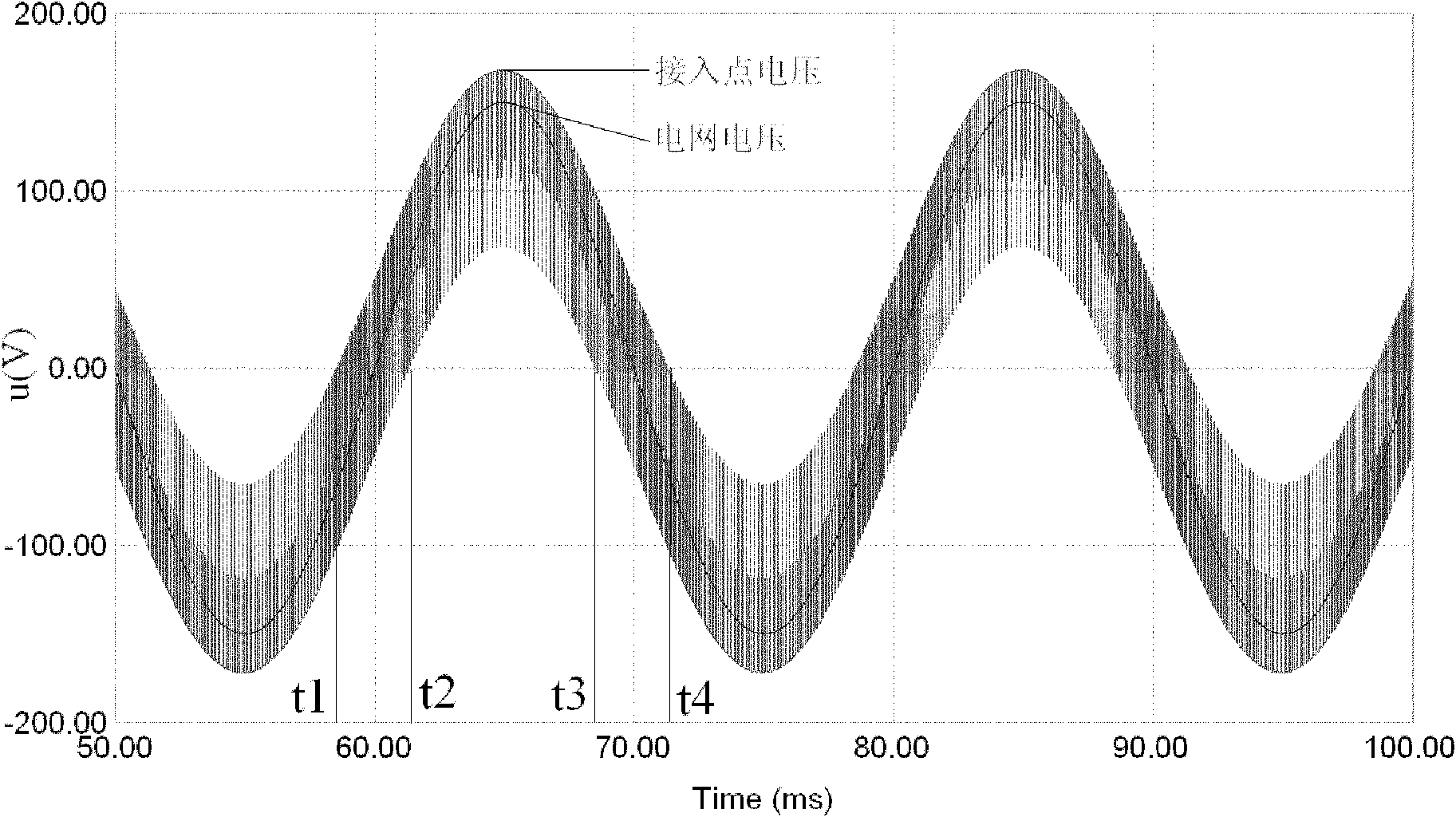
In addition to the output inductance of the photovoltaic inverter unit, there is also a connection line inductance between the photovoltaic inverter unit and the grid. Because the current is in the switching state, a switching voltage with ripples will be formed on the line inductance, resulting in the AC of the photovoltaic inverter access point. The sampled voltage no longer has a smooth sinusoidal waveform
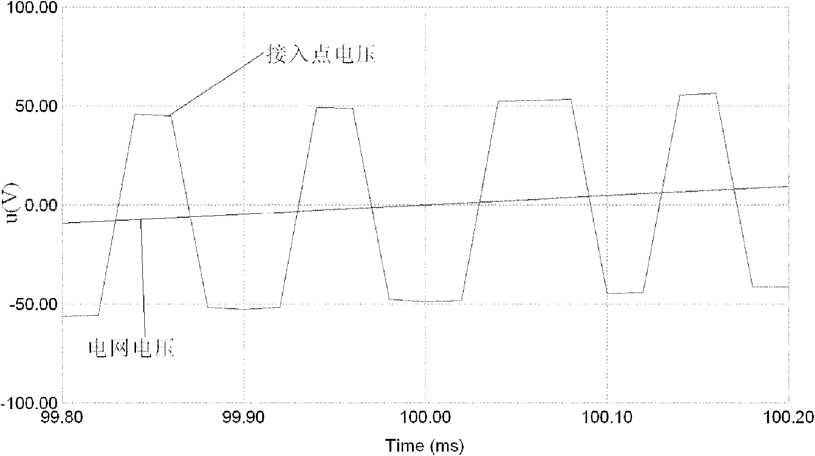
Especially when the output current of the photovoltaic inverter is large, the peak-to-peak voltage of the switch even exceeds the peak-to-peak voltage of the grid side, and there may be multiple voltage zero-crossing points in one cycle
At this time, it is no longer effective to use the traditional method of detecting the voltage zero-crossing position to determine the voltage phase. Even adding a pre-low-pass filter cannot completely eliminate the influence of the switching voltage, and cause voltage phase changes, resulting in large detection errors.
Some photovoltaic inverter units also use phase-locked loop (PLL) technology to detect the voltage phase of the grid. Although this method can accurately track the frequency of the grid, it cannot achieve accurate tracking of the voltage phase.
[0003] As far as the current literature can see, there is no very effective detection method for the voltage phase of the photovoltaic inverter access point in view of the interactive coupling effect of the line inductance and the switching process of the inverter, so as to realize the balance between the output current of the photovoltaic inverter and the grid voltage. accurate synchronization

Method used


Image

  • Access point voltage phase detection method of photovoltaic inverter by applying multiple zero-crossing points
  • Access point voltage phase detection method of photovoltaic inverter by applying multiple zero-crossing points
  • Access point voltage phase detection method of photovoltaic inverter by applying multiple zero-crossing points

Examples


Embodiment Construction

[0022] The present invention will be further described below in conjunction with the accompanying drawings and embodiments.

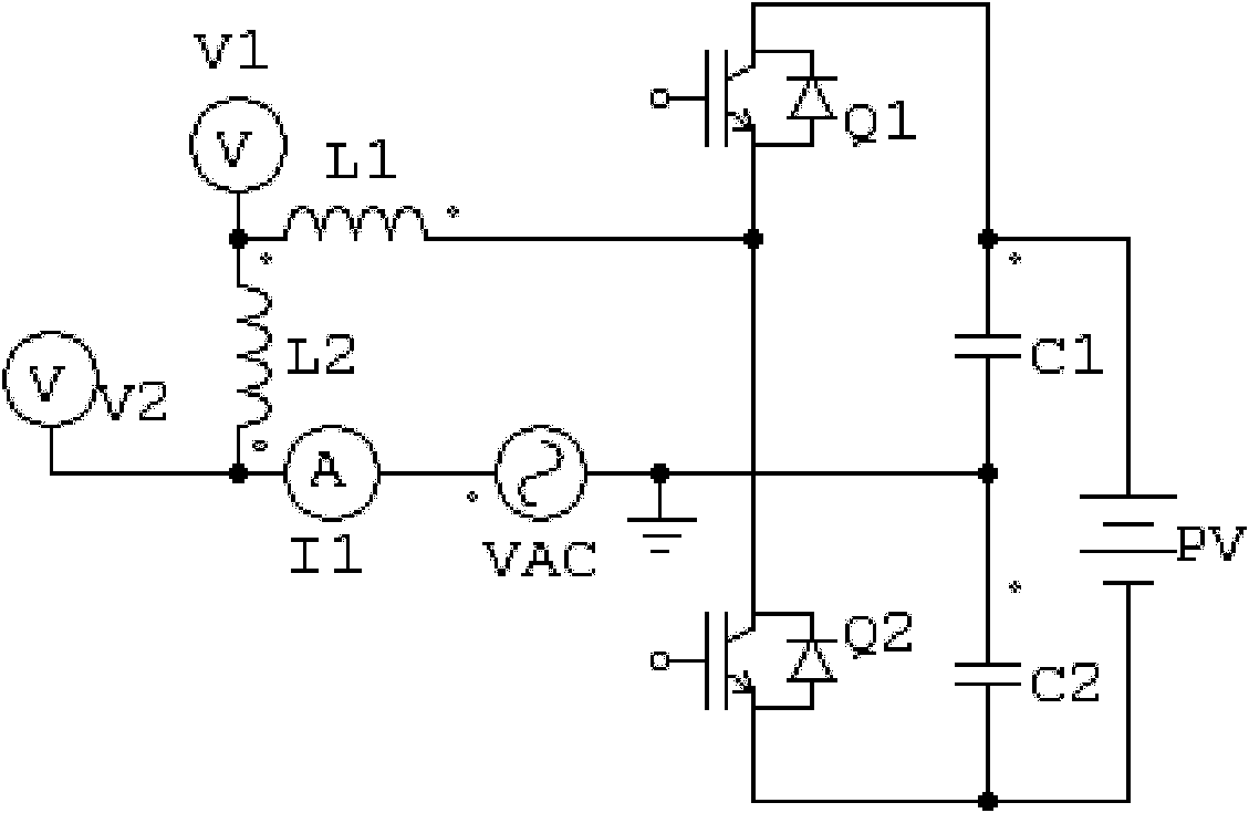
[0023] Considering the line inductance, the equivalent circuit of the photovoltaic inverter unit is as follows: figure 1 As shown, it uses a typical half-bridge topology. figure 1 , PV is the photovoltaic battery pack, C 1 and C 2 is the DC side capacitance, Q 1 and Q 2 is the IGBT switch tube, V 1 The voltage detection point for the photovoltaic inverter to connect to the distribution network, I 1 is the output current detection point of the photovoltaic inverter, L 1 is the output inductance of the inverter, L 2 is the line inductance, the photovoltaic inverter passes L 2 Incorporated into grid voltage node V AC .

[0024] 1) Dynamic switching process of photovoltaic inverter

[0025] Let flow through the inductor L 1 and L 2 The current is i 1 , V 1 The voltage at the point is u 1 . Because the switching frequency of power devices is...


PUM


Abstract

The invention relates to an access point voltage phase detection method of a line inductance based photovoltaic inverter by applying multiple zero-crossing points, which is simple, has small computation quantity, and can effectively detect the zero-crossing points and determine the phase of an actual grid voltage. The zero-crossing point moment of the actual gird voltage is accurately calculated through detecting before-and-after boundaries of the multiple zero-crossing point region by utilizing a unique characteristic that a multiple zero-crossing point region of the access point voltage wave form of the photovoltaic inverter is in strict bilateral symmetry on the zero-crossing points of the actual grid voltage, and further the specific phase at the current time in the grid voltage is determined .

Description

technical field [0001] The invention relates to a phase detection method based on line inductance for the voltage of a photovoltaic inverter access point with multiple zero-crossing points. Background technique [0002] Photovoltaic inverters generally work in the maximum power tracking (MPPT) state. At this time, its output current tracks the phase of the AC voltage of the grid and maintains synchronization. The ideal power factor is 1. In order to ensure the maximum output power state of the photovoltaic inverter, its output current must accurately track the phase of the grid voltage. The photovoltaic inverter unit generally realizes the phase synchronization of current and voltage by detecting the zero-crossing point of the three-phase voltage, which has the advantages of good real-time performance and rapid tracking. However, the actual line inductance is not zero. For high-frequency power electronic switching circuits, the inductive reactance is much greater than the r...

Claims


Application Information

Patent Timeline
IPC IPC(8): G01R25/00G01R19/175
Inventor 李庆民龚宇雷段玉兵王辉谭兴国
Owner SHANDONG UNIV
Learn More