Capturing optical lens

An optical lens and lens technology, applied in optics, optical components, instruments, etc., can solve problems such as increased system sensitivity, difficult manufacturing, and difficult control of yield rate, and achieve high resolution, reduced lens volume, and reduced sensitivity. Effect

Active Publication Date: 2012-07-25
LARGAN PRECISION
View PDF2 Cites 0 Cited by
  • Summary
  • Abstract
  • Description
  • Claims
  • Application Information

AI Technical Summary

Problems solved by technology

However, this method has its disadvantages. First, too many glass spherical mirror configurations make the system less free, which makes it difficult to shorten the total optical length of the system. Second, the manufacturing process of glass lens bonding is not easy, resulting in difficulties in manufacturing.
[0004] U.S. Patent No. 7,277,238 discloses a lens group composed of four independent lenses, including multiple aspherical lenses, which can effectively shorten the total optical length of the system and obtain good imaging quality, but because its aperture is set at the first Before the lens, the sensitivity of the system will be relatively improved, and it is difficult to control the yield in manufacturing

Method used


Image

  • Capturing optical lens
  • Capturing optical lens
  • Capturing optical lens

Examples


no. 1 example

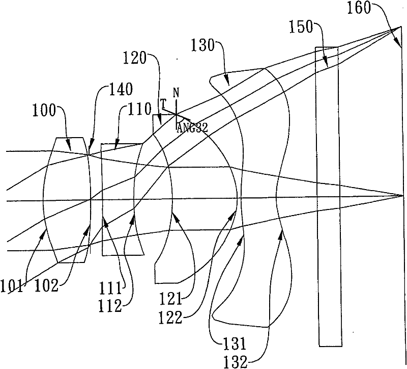
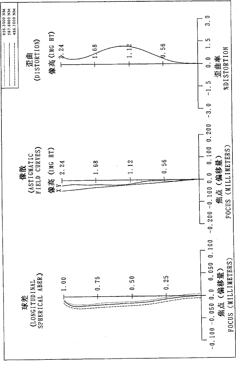
[0092] Please refer to the first embodiment of the present invention figure 1 , for the aberration curve of the first embodiment, please refer to figure 2 . The imaging optical lens of the first embodiment is mainly composed of four lenses, which include sequentially from the object side to the image side:

[0093] A first lens 100 with positive refractive power, its object-side surface 101 and image-side surface 102 are both convex, and its material is plastic, and the object-side surface 101 and image-side surface 102 of the first lens 100 are both aspherical;

[0094] A second lens 110 with negative refractive power, its object-side surface 111 and image-side surface 112 are both concave, and its material is plastic, and the object-side surface 111 and image-side surface 112 of the second lens 110 are both aspherical;

[0095] A third lens 120 with positive refractive power, its object-side surface 121 is concave and image-side surface 122 is convex, and its material is ...

no. 2 example

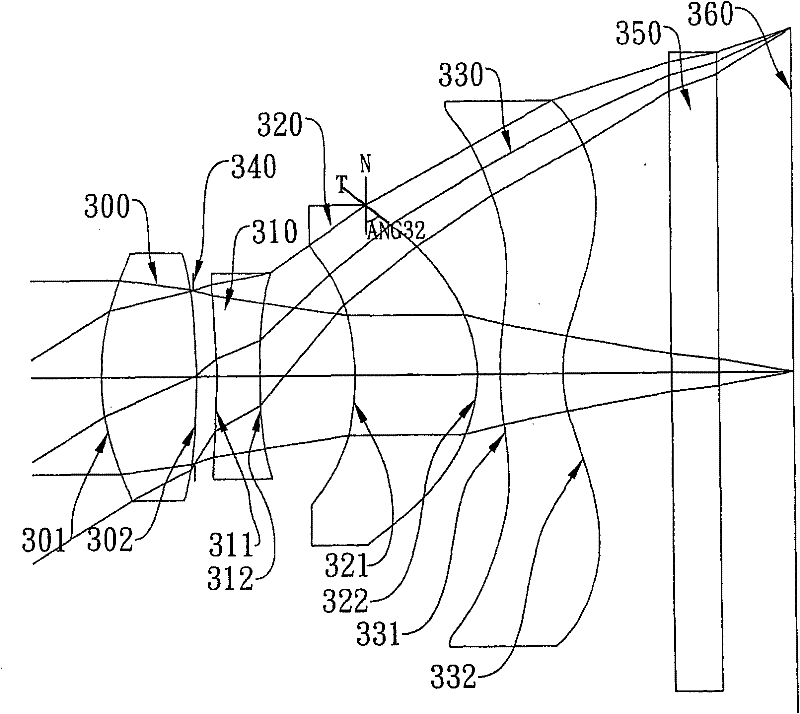
[0122] Please refer to the second embodiment of the present invention image 3 , for the aberration curve of the second embodiment, please refer to Figure 4 . The imaging optical lens of the second embodiment is mainly composed of four lenses, which include sequentially from the object side to the image side:

[0123] A first lens 300 with positive refractive power, its object-side surface 301 and image-side surface 302 are both convex, and its material is plastic, and the object-side surface 301 and image-side surface 302 of the first lens 300 are both aspherical;

[0124] A second lens 310 with negative refractive power, the object-side surface 311 and the image-side surface 312 are concave, the material is plastic, the object-side surface 311 and the image-side surface 312 of the second lens 310 are aspherical;

[0125] A third lens 320 with positive refractive power, its object-side surface 321 is concave and image-side surface 322 is convex, and its material is plastic...

no. 3 example

[0146] Please refer to the third embodiment of the present invention Figure 5 , for the aberration curve of the third embodiment, please refer to Figure 6 . The imaging optical lens of the third embodiment is mainly composed of four lenses, which sequentially include from the object side to the image side:

[0147] A first lens 500 with positive refractive power, its object-side surface 501 is convex and image-side surface 502 is concave, and its material is plastic. The object-side surface 501 and image-side surface 502 of the first lens 500 are both aspherical ;

[0148] A second lens 510 with negative refractive power, its object-side surface 511 and image-side surface 512 are both concave, and its material is plastic, and the object-side surface 511 and image-side surface 512 of the second lens 510 are both aspherical;

[0149] A third lens 520 with positive refractive power, its object-side surface 521 is concave and image-side surface 522 is convex, and its material...


PUM


Abstract

The invention discloses a capturing optical lens sequentially comprising a first lens, a second lens, a third lens and a fourth lens from an object side to an image side, wherein the first lens has a positive refractive power, the object side surface of the first lens is a convex surface, and the image side surface of the first lens is a convex surface; the second lens has a negative refractive power, and the object side surface of the third lens is a concave surface; the third lens has a positive refractive power, the image side surface of the first lens is a convex surface, and at least oneof the object side surface and the image side surface of the third lens is an aspheric surface; and the fourth lens has a negative refractive power, the object side surface of the fourth lens is a convex surface, the image side surface of the fourth lens is a concave surface, and the image side surface of the fourth lens is provided with at least one inflexion point. Only four lenses with the refractive powers are arranged in the capturing optical lens; the capturing optical lens is provided with an aperture and an electronic photosensitive device, a distance from the aperture to the electronic photosensitive device on an optical axis is SL, a distance from the object side surface of the first lens to the electronic photosensitive device on the optical axis is TTL, and the distances satisfy a relation of 0.75<SL / TTL<0.90. Through the arrangement mode of the lens group, the lens size can be effectively reduced, the sensitiveness of an optical system is reduced, and a higher resolution power can be obtained.

Description

technical field [0001] The invention relates to an image-taking optical lens, in particular to a miniaturized image-taking optical lens applied to a mobile phone camera. Background technique [0002] In recent years, with the rise of mobile phone cameras, the demand for miniaturized photographic lenses has increased day by day, and the photosensitive device of general photographic lenses is nothing more than a photosensitive coupling device (Charge Coupled Device, CCD) or a complementary metal oxide semiconductor device ( Complementary Metal-Oxide Semiconductor Sensor, CMOS Sensor), and due to the advancement of semiconductor process technology, the pixel area of ​​the photosensitive device is reduced, and the miniaturized photographic lens is gradually developing into the high-pixel field. Therefore, the requirements for imaging quality are also increasing. [0003] Traditional photographic lenses mounted on mobile phone cameras mostly use a front aperture and a four-piece ...

Claims


Application Information

Patent Timeline
Patent Type & Authority Patents(China)
IPC IPC(8): G02B13/00G02B13/18G02B1/04
Inventor 汤相岐蔡宗翰
Owner LARGAN PRECISION
Why Eureka
Try Eureka