Supercharge Your Innovation With Domain-Expert AI Agents!

Projection device

A projection device and light source device technology, applied in projection devices, optics, instruments, etc., can solve problems such as air intake resistance, blockage, and impact on the use of projectors, and achieve the effect of reducing maintenance

Inactive Publication Date: 2012-03-14
QISDA OPTRONICS (SUZHOU) CO LTD +1
View PDF0 Cites 0 Cited by
  • Summary
  • Abstract
  • Description
  • Claims
  • Application Information

AI Technical Summary

Problems solved by technology

But at the same time of ventilation, water vapor and dust in the air will also be brought in. If these water vapor and dust are attached to optical components, especially liquid crystal panels, it will affect the optical performance of optical components. In order to minimize the influence of dust, The existing technology often installs a filter made of oil screen or sponge on the air inlet. On the one hand, adding a filter will produce a certain air intake resistance, and on the other hand, it will be blocked after a long time of use. , will have a serious impact on the use of the projector, so the filter must be cleaned regularly, which brings great trouble to the user

Method used


Image

  • Projection device
  • Projection device
  • Projection device

Examples


Embodiment Construction

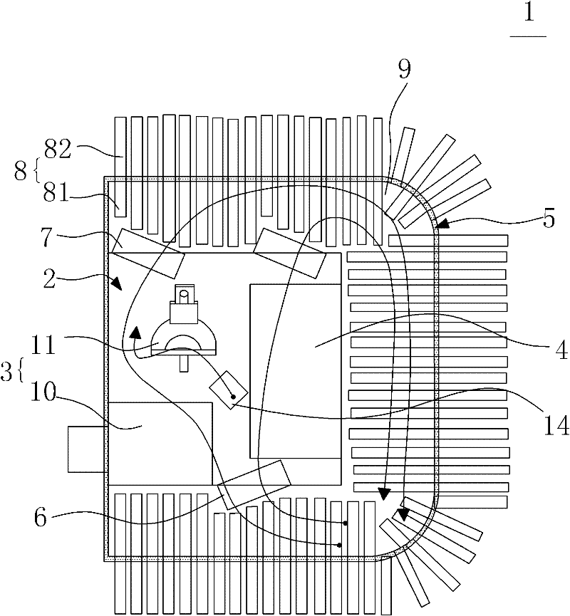
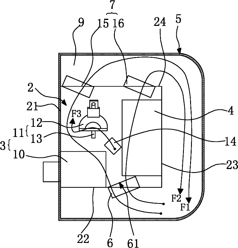
[0019] See Figure 1-Figure 2 , figure 1 Shown is a schematic diagram of a first embodiment of a projection device according to the present invention, figure 2 shown as figure 1 The schematic diagram of the heat dissipation unit is not shown in the projection device. The present invention provides a projection device 1 , which includes an inner casing 2 , an optical system 3 and a circuit system 4 accommodated in the inner casing 2 , an outer casing 5 , an air blowing fan 6 , an exhaust fan 7 and a heat dissipation unit 8 .

[0020] The inner housing 2 includes a first side wall 21 and a third side wall 23 oppositely arranged, a second side wall 22 and a fourth side wall 24 adjacent to the first side wall 21 and the third side wall 23, that is, the first side wall 21 and the third side wall 23 One side wall 21 is set opposite to the third side wall 23, the second side wall 22 is set opposite to the fourth side wall 24, and the inner casing 2 is made of, for example, a mate...


PUM


Abstract

The invention discloses a projection device which comprises an inner housing, an optical system and a circuit system accommodated in the inner housing, an outer housing, a blowing fan, an exhaust fan and a heat radiation unit. The inner housing and the outer housing form a U-shaped region, and the blowing fan is arranged on the second side wall of the inner housing and can suck the air from the U-shaped region and blow the air into the inner housing; the exhaust fan is arranged on the fourth side wall of the inner housing and can exhaust air flow in the inner housing to the U-shaped region; and the heat radiation unit comprises a first radiator arranged in the U-shaped region and a second radiator arranged on the outer side of the outer housing, the first radiator and the air flow in the inner housing form forced convection, and the second radiator and the air flow outside the outer housing form natural convection, thereby cooling the air flow positioned in the U-shaped region. The projection device comprises the internal circulating air flow and does not need to change the air with environment directly, thereby preventing water vapor and dust in the external environment from being brought into the inner housing along with the cooling air flow.

Description

technical field [0001] The present invention relates to a projection device, in particular to a projection device capable of achieving waterproof and dustproof effects. Background technique [0002] During the working process of the projector, a large amount of heat will be generated. The heat mainly comes from the light bulb. Except a part of the energy of the light bulb becomes light energy, most of the energy is dissipated in the projector in the form of heat. In addition, the light in the optical engine module Optical components will also absorb part of the light that cannot pass through and generate heat. If the heat is not dissipated in time, it will seriously affect the normal operation and service life of the projector. The heat generated in the process is dissipated in time. This heat dissipation mechanism generally includes a plurality of fans of different sizes and corresponding air ducts, which are used to inhale air from the outside for forced ventilation durin...

Claims


Application Information

Patent Timeline
Patent Type & Authority Patents(China)
IPC IPC(8): G03B21/16H05K7/20
Inventor 萧启宏
Owner QISDA OPTRONICS (SUZHOU) CO LTD
Features
  • R&D
  • Intellectual Property
  • Life Sciences
  • Materials
  • Tech Scout
  • Unparalleled Data Quality
  • Higher Quality Content
  • 60% Fewer Hallucinations
Learn More