Speed measurement control device for motor

A control device and speed measurement technology, which is applied to electromechanical devices, manufacturing motor generators, electrical components, etc., can solve the problems of increased installation space, no speed measurement device, and increased motor operating noise, and is convenient for packaging and transportation. , The effect of eliminating unsafe hidden dangers and accurate speed control

Inactive Publication Date: 2011-05-25
胡磊
View PDF5 Cites 6 Cited by
  • Summary
  • Abstract
  • Description
  • Claims
  • Application Information

AI Technical Summary

Problems solved by technology

[0002] The existing control motor used in the centrifuge refrigeration studio has a working condition of 25,000 rpm and high speed, but there is no speed measuring device, which limits the application of the motor. In order to increase the speed measuring control function, the user can only install it under the motor. A speed control device
After the speed measurement control device is installed, and the tail end of the motor shaft protrudes outside the lower end cover of the motor, the overall length of the motor increases, resulting in an increase in the space required for the installation of the motor product, and additional product stands are required for product placement, packaging and transportation. More parts and lengthening of the product increase the use and installation difficulty of the motor and the original matching user equipment. For example, different user equipment has different installation size requirements, which often cause installation difficulties or insufficient installation space, which increases the User usage and maintenance costs
In addition, the bearing device for the motor is easy to be squeezed and damaged at the junction of the motor shaft and the motor end cover due to high-speed operation, heat generation, parking, cooling, deformation, etc., resulting in increased motor operating noise, increased vibration, and reduced product qualification rate , the waste of raw materials is large, and the supporting equipment cannot work normally and safely

Method used


Image

  • Speed measurement control device for motor
  • Speed measurement control device for motor
  • Speed measurement control device for motor

Examples


Embodiment Construction

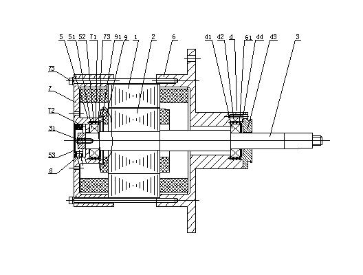
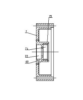
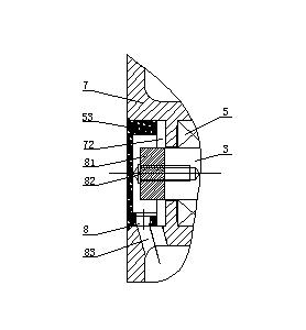
[0029] As shown in the accompanying drawings, a speed measurement control device for a motor includes a motor shaft 3 interspersed in the center of the stator core 1 and the rotor core 2, and the motor shaft 3 is respectively fixed to the motor through an upper bearing device 4 and a lower bearing device 5. Among the upper end cover 6 and the lower end cover 7 of the motor, the upper bearing device 4 includes an upper end cover bearing 41 fixed on the motor main shaft 3, and the upper end cover bearing 41 is arranged in the recessed platform 61 of the upper end cover 6 of the motor, and the upper end cover bearing of the recessed platform 61 41 The upper bearing elastic element 42 is arranged radially, and the upper sealing cover plate 43 is arranged axially of the upper bearing elastic element 42; the lower bearing device 5 includes a lower end cover bearing 51 fixed on the motor main shaft 3, and the lower end cover bearing 51 is arranged on the lower end cover of the motor 7...


PUM


Abstract

The invention discloses a speed measurement control device for a motor. The speed measurement control device comprises a motor main shaft inserted in a stator iron core and a rotor iron core, wherein the motor main shaft is fixed in an upper end cover and a lower end cover of the motor through an upper bearing device and a lower bearing device respectively; the upper bearing device comprises an upper end cover bearing fixed on the main shaft; the upper end cover bearing is arranged in a concave platform of the upper end cover of the motor; an upper bearing elastic component is radially arranged on the upper end cover bearing in the concave platform; an upper sealing cover plate is axially arranged on the upper bearing elastic component; the lower bearing device comprises a lower end coverbearing fixed on the main shaft; the lower end cover bearing is arranged in an inner concave platform of the lower end cover of the motor; a lower bearing elastic component is radially arranged on the lower end cover bearing in the inner concave platform; a lower sealing cover plate is arranged in an outer concave platform of the lower end cover of the motor; and signal converters are arranged incavities of the lower sealing cover plate and the outer concave platform. The scheme provided by the invention overcomes the defect that the motor application is limited because the conventional motor is not provided with the speed measurement control device and the like; besides, the speed measurement control device is suitable for various control motors.

Description

technical field [0001] The invention relates to a speed measuring control device for a motor. Background technique [0002] The existing control motor used in the centrifuge refrigeration studio has a working condition of 25,000 rpm and high speed, but there is no speed measuring device, which limits the application of the motor. In order to increase the speed measuring control function, the user can only install it under the motor. A speed control device. After the speed measurement control device is installed, and the tail end of the motor shaft protrudes outside the lower end cover of the motor, the overall length of the motor increases, resulting in an increase in the space required for the installation of the motor product, and additional product stands are required for product placement, packaging and transportation. More parts and lengthening of the product increase the use and installation difficulty of the motor and the original matching user equipment. For example...

Claims


Application Information

Patent Timeline
Patent Type & Authority Applications(China)
IPC IPC(8): H02K11/00H02K5/04H02K5/24H02K5/16H02K15/14H02K15/00H02K11/21
Inventor 胡永光胡婧胡磊
Owner 胡磊
Why Eureka
Try Eureka