Ethernet power supply end equipment as well as system and method thereof for realizing power supply

A technology for power supply terminal equipment and power receiving terminal equipment is applied in the field of power supply terminal equipment and its realization of power supply. The effect of improving processing capacity and increasing power supply

Inactive Publication Date: 2011-05-25
WUHAN ZHONGXING SOFTWARE CO LTD
View PDF3 Cites 18 Cited by
  • Summary
  • Abstract
  • Description
  • Claims
  • Application Information

AI Technical Summary

Problems solved by technology

However, some PD designs only use 1-2 wire pairs and 3-6 wire pairs to receive power, or only use 4-5 wire pairs and 7-8 wire pairs to receive power
In this way, the incompatibility with the PSE is increased, causing the PSE to fail to supply power to these PDs
[0005] In addition, when the PSE only uses 1-2 wire pairs and 3-6 wire pairs for external power supply, if the center tap of the transformer on the 1-2 wire pair and 3-6 wire pair of the PSE or PD and its control unit (that is, the respective management If the connection is abnormal, the normal work of both PSE and PD cannot be realized.
When the PSE only uses 4-5 wire pairs and 7-8 wire pairs for external power supply, if it is connected to the PSE or PD with 4 wires (used to use 1-2 wire pairs and 3-6 wires to transmit 100M signals), it is also will not be able to achieve the normal work of both parties
[0006] Moreover, even if a normal 8-wire Ethernet cable is used to connect the PSE and PD, if there is no abnormality in the PSE and PD equipment, the power supply power of the PSE to the PD is only 30W or less, and it is impossible to achieve a higher power supply.
[0007] To sum up, it can be seen that the selection of PSE port power supply wire pairs in the prior art either uses 1, 2 wire pairs and 3, 6 wire pairs, or uses 4, 5 wire pairs and 7, 8 wire pairs, or uses all four wire pairs. Each line pair is in a fixed mode, which cannot flexibly deal with abnormal problems such as the PD’s line pair or the connection line in the device, or cannot achieve the power limit of more than 30W external power supply

Method used


Image

  • Ethernet power supply end equipment as well as system and method thereof for realizing power supply
  • Ethernet power supply end equipment as well as system and method thereof for realizing power supply
  • Ethernet power supply end equipment as well as system and method thereof for realizing power supply

Examples


Embodiment Construction

[0040] The technical solutions of the present invention will be described in detail below in conjunction with the accompanying drawings and preferred embodiments. The following examples are only used to illustrate and explain the present invention, but not to limit the technical solution of the present invention. It should be noted that, in the case of no conflict, the following exemplary embodiments and the features in the embodiments can be combined with each other.

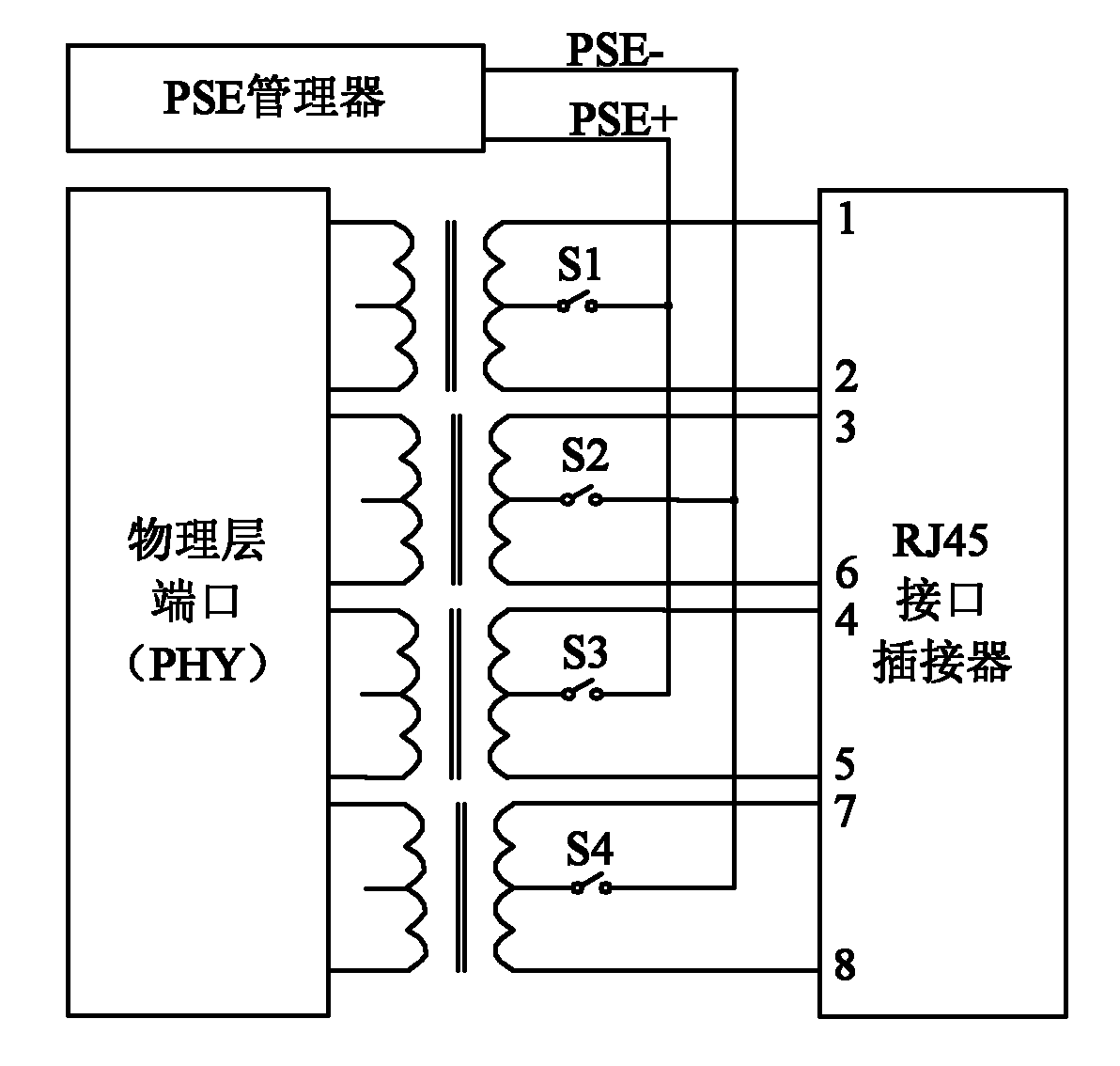
[0041] Such as figure 2 Shown is the internal circuit structure of a PSE embodiment of the present invention, four switches S1, S2, S3, S4 are respectively connected between the four transformer center taps of the physical layer port of the PSE and the PSE manager, wherein:

[0042] The switch S1 is connected between the PSE+ terminal of the PSE manager and the center tap of the 1-2 line pair transformer, the switch S2 is connected between the PSE- terminal of the PSE manager and the center tap of the 3-6 line ...


PUM


Abstract

The invention discloses Ethernet power supply end equipment as well as a system and method thereof for realizing power supply. The Ethernet power supply equipment comprises two pairs of transformers of a physical-layer port, and a power supply end equipment manager; in addition, a pair of switches is connected between each pair of transformers and the power supply end equipment manager respectively; wherein one switch of each pair of switches is connected between the positive end of the power supply end equipment manager and the central tap of one transformer of each pair of transformers, and the other switch in each pair of switched is connected between the negative end of the power supply end equipment manager and the central tap of the other transformer of each pair of transformers. By means of the invention, the compatibility and the flexibility of the entire POE (Power Over Ethernet) system are improved, power loss on lines is reduced, meanwhile, the operation management by a user is simplified.

Description

technical field [0001] The invention relates to Power Over Ethernet (POE, Power Over Ethernet) technology in the field of data communication, in particular to a power supply end device and a system and method for realizing power supply. Background technique [0002] With the development of communication product technology, without any changes to the existing Ethernet wiring infrastructure, the power supply equipment (PSE, Power Sourcing Equipment) is some IP-based terminals (such as IP phones, wireless LAN access Point AP, network camera, etc.) while transmitting data signals, it can also use POE technology to provide DC power supply for such devices. These IP-based terminals do not need to install power equipment separately and connect power cables for this purpose, and are called powered end devices (PD, PowerDevice). More and more network devices have the POE function for powering these PDs, including routers and switches. [0003] The Ethernet cable connected to the po...

Claims


Application Information

Patent Timeline
Patent Type & Authority Applications(China)
IPC IPC(8): H04L12/10
Inventor 尚迎春
Owner WUHAN ZHONGXING SOFTWARE CO LTD
Why Eureka
Try Eureka