Data transmission bus system

A technology of data transmission and bus system, which is applied in the direction of bus network, data exchange through path configuration, exposure device of photo-plate making process, etc. And other issues

Active Publication Date: 2011-05-25
SHANGHAI MICRO ELECTRONICS EQUIP (GRP) CO LTD
View PDF4 Cites 5 Cited by
  • Summary
  • Abstract
  • Description
  • Claims
  • Application Information

AI Technical Summary

Problems solved by technology

[0011] 1) The bus transmission is initiated by the data processing module. When there are multiple data processing modules on the bus, there is no guarantee that only one data processing module initiates data transmission at a certain moment. When multiple data modules initiate data transmission at the same time, bus conflicts

Method used


Image

  • Data transmission bus system
  • Data transmission bus system
  • Data transmission bus system

Examples


Embodiment Construction

[0028] The invention provides a data transmission bus system based on queue mechanism, asynchronous timing planning and data synchronous broadcasting. The bus system includes a data transmission bus, a bus control module, a raw data acquisition module, and multiple data processing modules.

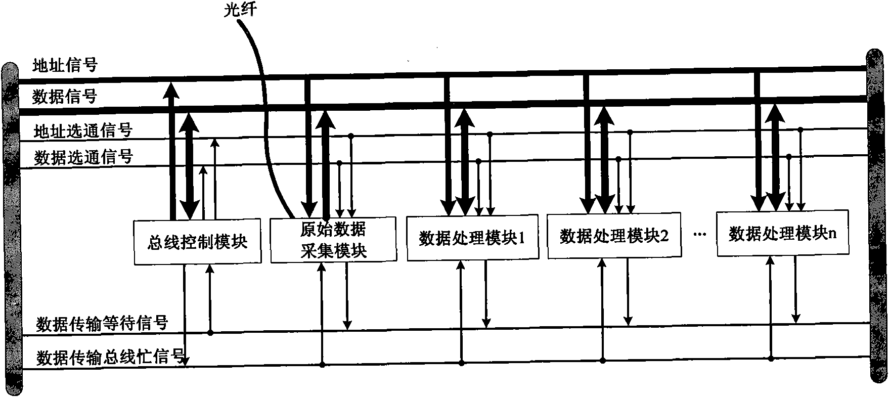
[0029] Now according to figure 2 Each module in the MDB system according to the present invention is described in detail. Such as figure 2 As shown, the data transmission bus includes four types of signal lines: address signal lines, data signal lines, control signal lines and status signal lines. In this embodiment, the data transmission bus is a non-address-data multiplexed broadcast bus. For ease of description, the data transmission bus will be collectively referred to as a motion data transmission bus (MDB-Motion Data Bus) hereinafter. The bus control module, the raw data acquisition module and the data processing module respectively include an MDB bus interface for data interac...


PUM


Abstract

The invention discloses a data transmission bus system, which comprises a data transmission bus, a bus control module, a raw data acquisition module and a plurality of data processing modules, wherein the bus control module specifies a data transmission source in the raw data acquisition module or the data processing modules, receives a data transmission waiting signal from the data transmission source, controls the data transmission source to output data according to a current transmission state, controls the data processing modules to receive the data, and simultaneously outputs a data transmission bus busying signal. The data transmission bus system provided by the invention controls data transmission by the bus control module, and can ensure that only one data processing module initiates the data transmission at a certain time, and avoid bus contention when the plurality of data processing modules simultaneously initiate the data transmission.

Description

technical field [0001] The present invention relates to a motion data transmission bus system of a synchronous control system of a step-scan projection lithography machine, and furthermore, relates to a motion data transmission bus system based on a queue mechanism, asynchronous timing planning, and data synchronous broadcasting, and based on The data transmission method of the data transmission bus system. Background technique [0002] Photolithography is the most critical process in the process of integrated circuit processing, so the lithography machine is the most critical equipment in the process of integrated circuit processing. [0003] figure 1 Part (a) is a structural schematic diagram of the workpiece stage, mask stage and slit of the step-and-scan projection lithography machine. The beam 10 is projected onto the mask 13 after passing through the slit formed by the two blades 11 and 12, and the mask passes through the beam at a set speed at a constant speed. Sim...

Claims


Application Information

Patent Timeline
IPC IPC(8): H04L12/40G03F7/20
Inventor 方欣张志钢周金明
Owner SHANGHAI MICRO ELECTRONICS EQUIP (GRP) CO LTD
Why Eureka
Try Eureka