
Integrated routing setting method and device

A channel and logical link technology, applied in the field of network communication, can solve the problems of not considering the multi-fiber situation, not being able to conduct reasonable routing of services, and not being able to better consider the impact of resource allocation, etc., to achieve the effect of ensuring network load

Active Publication Date: 2011-05-25
CHINA TELECOM CORP LTD
View PDF5 Cites 10 Cited by
  • Summary
  • Abstract
  • Description
  • Claims
  • Application Information

AI Technical Summary

Problems solved by technology

[0005] At present, there are some joint routing setting methods for solving IP / WDM network routing problems. However, the inventors have found that these existing routing setting methods have the following limitations: first, most of the methods for solving the routing problem belong to fixed selection. Fixed Routing (FR) strategy, that is, when establishing a label switching path (Lab Switch Path, LSP) for a pair of nodes, the LSP is established on the only route, which cannot better consider the impact of resource allocation on the entire network. This will not be conducive to the balance of business between node pairs; second, most of the research on joint routing is based on the single-fiber auxiliary graph model, without considering the multi-fiber situation, which makes the analysis of the performance of the routing setting method one-sided; third, when there is When a service enters a network with a small maximum bearer bandwidth of a single wavelength from a network with a large maximum bearer bandwidth of a single wavelength, the service cannot be properly routed

Method used


Image

  • Integrated routing setting method and device
  • Integrated routing setting method and device
  • Integrated routing setting method and device

Examples


Embodiment Construction

[0036] The present invention will be described more fully hereinafter with reference to the accompanying drawings, in which exemplary embodiments of the invention are illustrated. The exemplary embodiments of the present invention and their descriptions are used to explain the present invention, but do not constitute an improper limitation of the present invention.

[0037] The following description of at least one exemplary embodiment is merely illustrative in nature and in no way taken as limiting the invention, its application or uses.

[0038] For a WDM network with a certain system, assume that the single-wavelength bandwidth capacity of the network is A, and the bandwidth requirement of the arriving service is B. When B>A, it is called "big bandwidth requirement business", referred to as large business; and B< In case A, it is called "small bandwidth requirement service", or small service for short. When a service enters a network with a larger maximum bearer bandwidth ...


PUM


Abstract

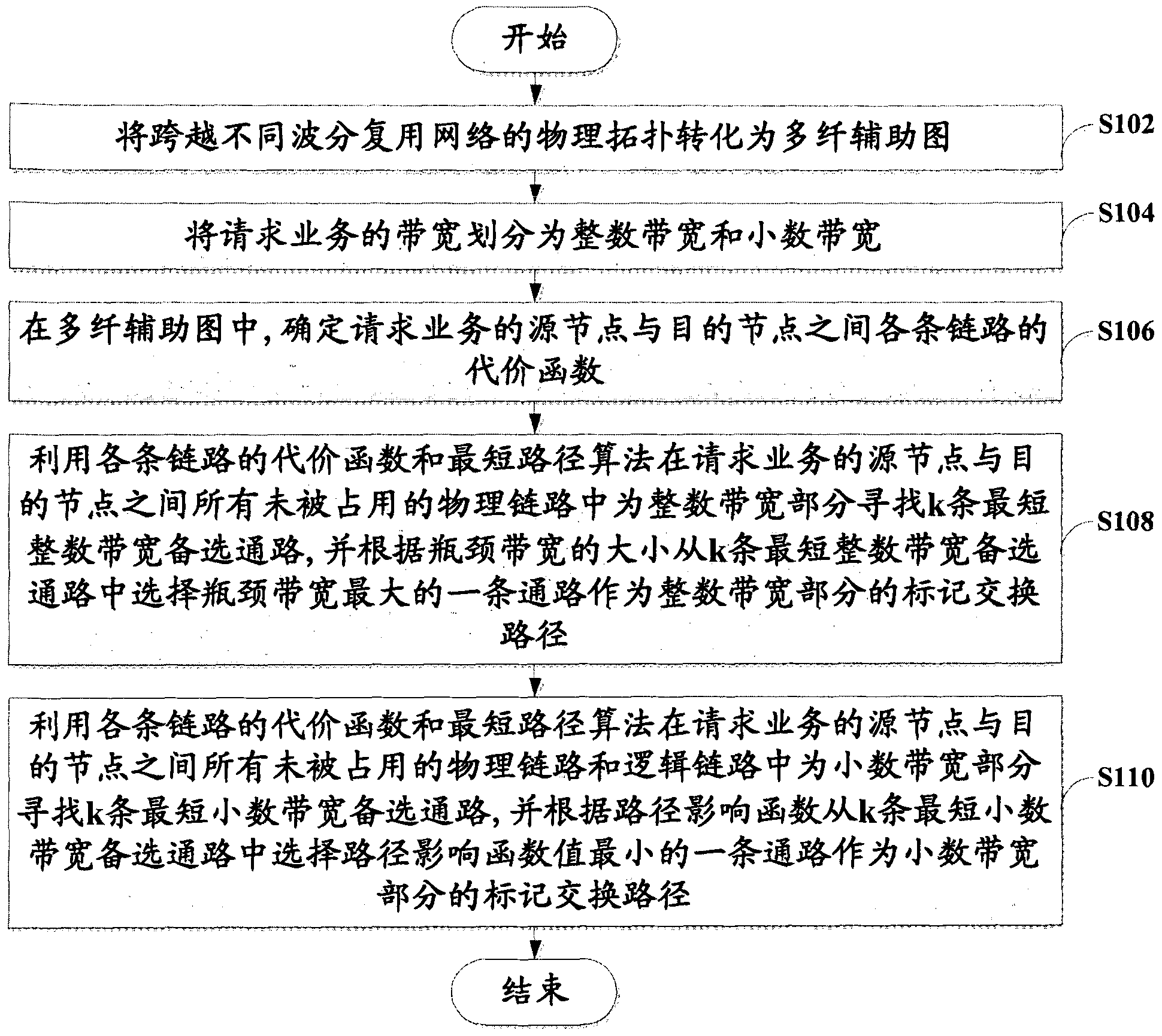
The invention discloses an integrated routing setting method and an integrated routing setting device. The method comprises the following steps of: converting a physical topology crossing different wavelength division multiplexing networks into a multi-fiber auxiliary chart; dividing a bandwidth of a request service into an integral bandwidth and a decimal bandwidth; determining a cost function of each chain between a source node and a destination node of the request service; seeking k shortest integral bandwidth alternative channels for the integral bandwidth part, and selecting one channel with the maximum bottleneck bandwidth from the k shortest integral bandwidth alternative channels as a label switching path of the integral bandwidth part; and seeking k shortest decimal bandwidth alternative channels for the decimal bandwidth part, and selecting one channel with the minimum path influence function value from the k shortest decimal bandwidth alternative channels as a label switching path of the decimal bandwidth part. By the method and the device, the bandwidth of the service is divided into an integral bandwidth part and a decimal bandwidth part; and the label switching paths are determined for the two bandwidth parts according to the cost function and a path influence function respectively.

Description

technical field [0001] The present invention relates to the field of network communication, in particular, to a joint routing setting method and device. Background technique [0002] There are three most popular IP transmission technologies at present, namely, IP over ATM (Asynchronous Transfer Mode), IP over SDH (Synchronous Digital Hierarchy) and IPover WDM (Wavelength Division Multiplex). These three IP transmission technologies all play their due roles in different periods of telecommunication network development and in different parts of the network, and the three will coexist and complement each other. But from a future-oriented perspective, IP over WDM will be the most viable technology, and its huge bandwidth potential matches the explosive growth of IP services. Therefore, this is the most ideal transmission for IP services. Technology will become the dominant transmission technology of the future network, especially the backbone network. [0003] The research sho...

Claims


Application Information

Patent Timeline
Patent Type & Authority Applications(China)
IPC IPC(8): H04L12/56H04Q11/00H04L45/125
Inventor 薄明霞陈军王渭清赵洪波俞韶桢
Owner CHINA TELECOM CORP LTD
Learn More