Eureka AIR delivers breakthrough ideas for toughest innovation challenges, trusted by R&D personnel around the world.

Method and device for allocating carrier resources to user equipment (UE)

A technology for allocating carriers and user terminals, applied in wireless communication, electrical components, etc., can solve the problems of UE throughput and rate performance degradation, not considering throughput, and difficult base station judgment, to ensure superiority, reduce the number, The effect of reducing system overhead

Active Publication Date: 2011-05-25
常熟市知识产权运营中心有限公司
View PDF4 Cites 3 Cited by
  • Summary
  • Abstract
  • Description
  • Claims
  • Application Information

AI Technical Summary

Problems solved by technology

The biggest problem in carrier aggregation is that the path loss and propagation conditions experienced by the aggregated carriers are inconsistent, which makes it difficult for the base station to make a unified decision when performing resource scheduling, that is, a certain decision condition is suitable for a certain type of carrier Carriers with path loss and propagation conditions, but carriers with other types of path loss and propagation conditions that are not suitable for carrier aggregation
[0004] At present, the carrier aggregation discussed in LTE-Advanced does not take into account the impact of inter-cell interference that plays an important role in inter-cell UE throughput and UE average throughput. When allocating carrier resources for user terminals, all components after aggregation In this way, if the aggregated carrier part suffers severe inter-cell interference, even if a larger bandwidth is obtained, the throughput of UEs using this part of the aggregated carrier will be reduced due to severe inter-cell interference and rate performance are severely degraded, thereby negating the benefits of carrier aggregation

Method used


Image

  • Method and device for allocating carrier resources to user equipment (UE)
  • Method and device for allocating carrier resources to user equipment (UE)
  • Method and device for allocating carrier resources to user equipment (UE)

Examples


Embodiment Construction

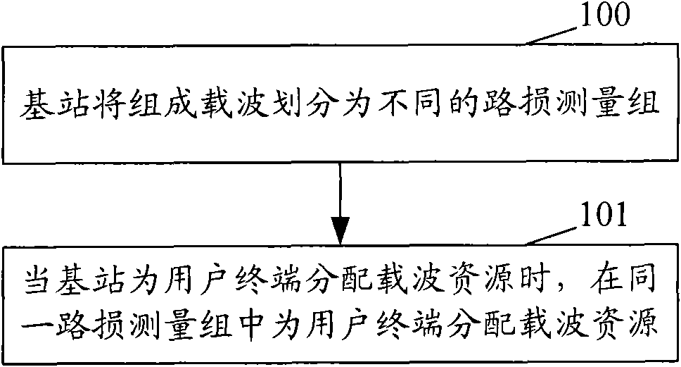
[0027] figure 1 It is a flowchart of a method for allocating carrier resources to a user terminal according to the present invention, such as figure 1 As shown, including the following steps:

[0028] Step 100: The base station divides the component carriers into different path loss measurement groups.

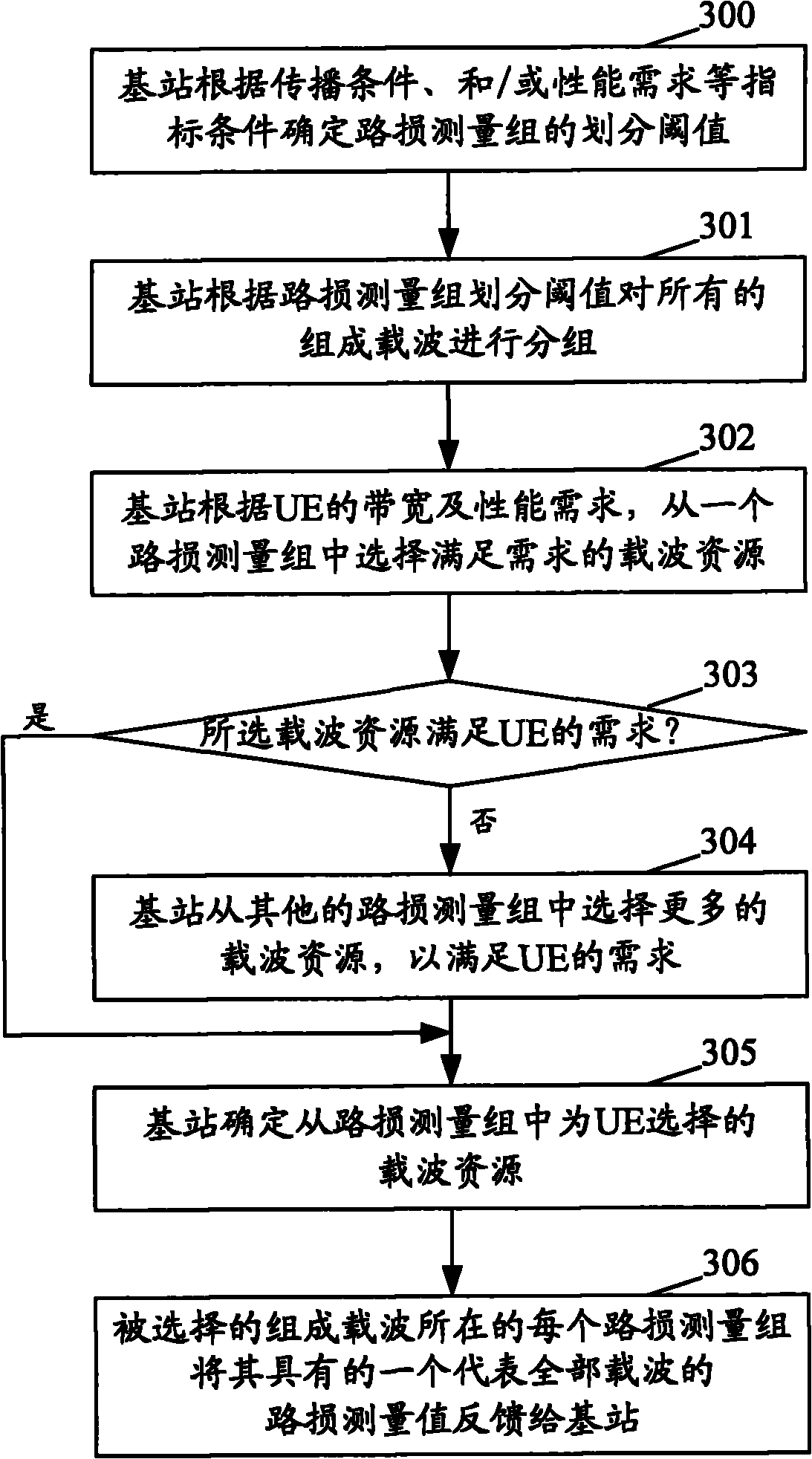
[0029] Since there are multiple different component carriers during carrier aggregation, this step includes: according to different component carrier index conditions, such as propagation conditions such as line-of-sight transmission or non-line-of-sight transmission, and / or performance requirements such as interference conditions , And / or rate, and / or throughput, etc., divide the component carriers into multiple different path loss measurement groups. That is, the same path loss measurement group includes all user terminals with similar or same path loss conditions.

[0030] Step 101: When the base station allocates carrier resources for user terminals, it allocates carrier resourc...


PUM


Abstract

The invention provides a method and a device for allocating carrier resources to user equipment (UE). The method comprises the following steps that: a base station divides component carriers into different path loss measuring groups; and when allocating the carrier resources to the UE, the base station allocates the carrier resources to the UE in the same path loss measuring group, and the UE is needed to feed only a path loss measuring value shared by all carriers back to the base station at the time. In the method, the path loss measuring groups are arranged, so that the superiority of carrier aggregation is ensured, the number of path loss measuring feedback values is reduced, and system overhead is effectively reduced.

Description

Technical field [0001] The present invention relates to carrier aggregation technology, and in particular to a method and device for allocating carrier resources for user terminals in carrier aggregation. Background technique [0002] In the next-generation broadband wireless communication network, how to support a larger bandwidth in the wireless communication network under the bandwidth of the current wireless communication system is to improve the throughput of user terminals (UE, User Equipment) between cells and the average user terminal A key factor in throughput and facing severe challenges. At present, the Long Term Evolution (LTE) of the Third Generation Partnership Project (3GPP) has proposed the use of carrier aggregation to effectively support greater bandwidth in the current wireless communication system. Meet the requirements for throughput, peak rate and other indicators in the new generation of wireless standards. [0003] Carrier aggregation is a key technology t...

Claims


Application Information

Patent Timeline
IPC IPC(8): H04W72/04
Inventor 魏巍
Owner 常熟市知识产权运营中心有限公司
Why Eureka
Eureka Blog
Learn More