End wall of a pulp dryer, pulp dryer, and method for observing the inner parts of a pulp dryer

A dryer and end wall technology, applied in the direction of the dryer section, pulp dehydration, wing fan arrangement, etc., to achieve the effects of reducing heat loss, reducing heat loss, and improving drying performance

Active Publication Date: 2011-05-25
METSO PAPER INC
View PDF0 Cites 2 Cited by
  • Summary
  • Abstract
  • Description
  • Claims
  • Application Information

AI Technical Summary

Problems solved by technology

However, this solution does not fully allow for relatively easy execution of maintenance operations in the pulp dryer in all cases

Method used


Image

  • End wall of a pulp dryer, pulp dryer, and method for observing the inner parts of a pulp dryer
  • End wall of a pulp dryer, pulp dryer, and method for observing the inner parts of a pulp dryer
  • End wall of a pulp dryer, pulp dryer, and method for observing the inner parts of a pulp dryer

Examples


Embodiment Construction

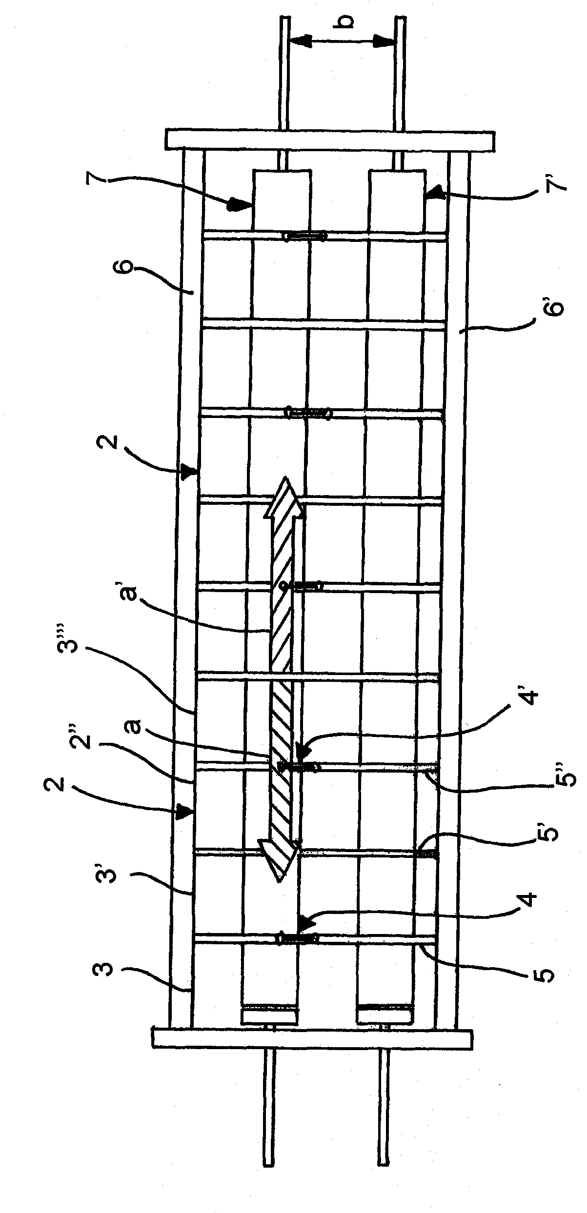
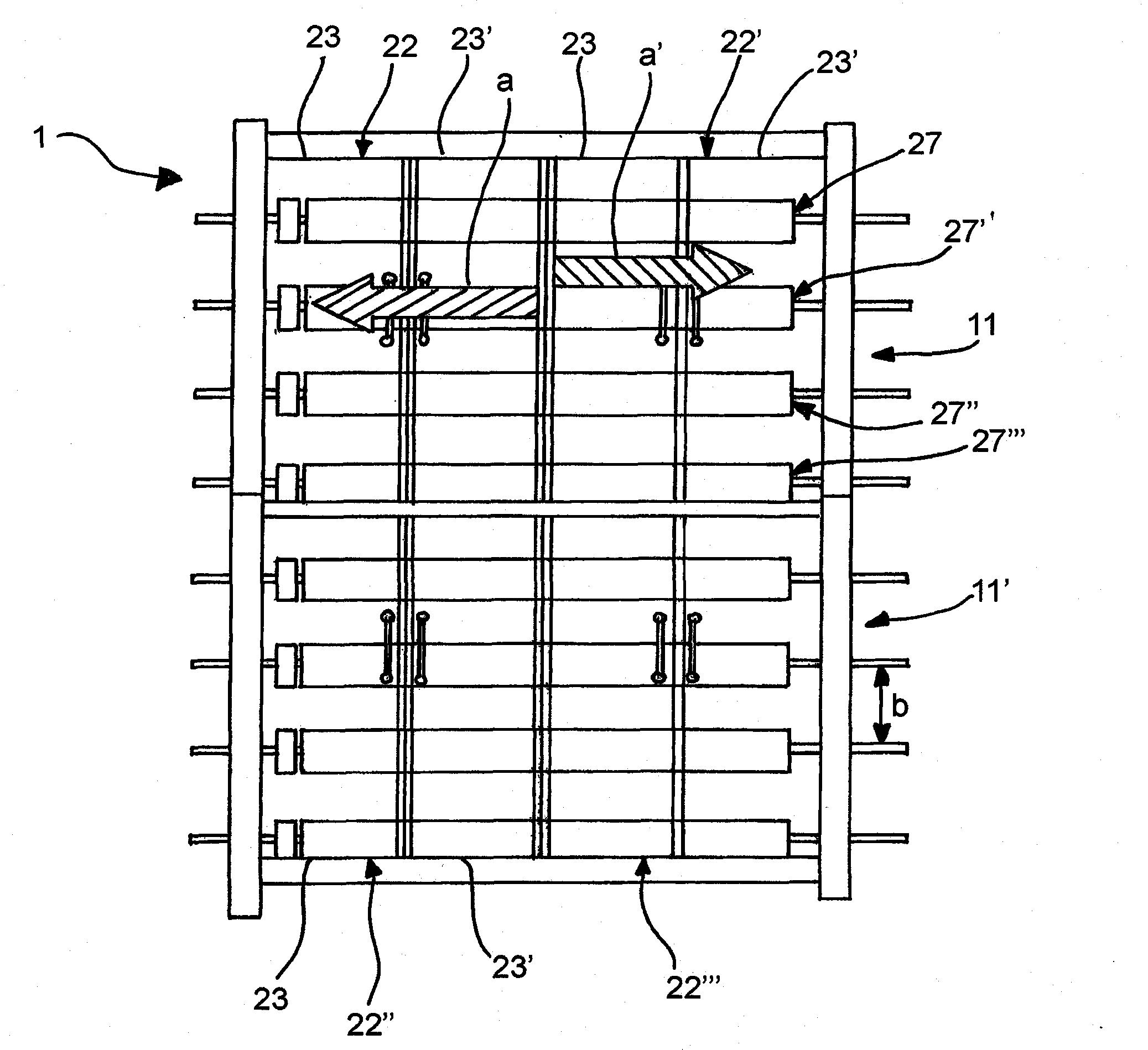
[0064] figure 1 A part of the end wall of a pulp dryer according to an embodiment of the present invention is shown. The figure shows two end wall members 2, 2', of which the first end wall member 2 can be arranged at a position open towards the operating side of the pulp dryer, and the second end wall member 2'can be arranged towards the pulp web. The position where the drive side of the dryer is open. The opening direction of the end wall members 2, 2’ is in figure 1 Indicated by arrows a, a'. The end wall member 2 includes four partial members 3, 3', 3", 3"', and the partial members 3, 3', 3", 3"' are arranged to open to the operating side in a folding door manner. The two partial members 3, 3'are provided with moving devices 4, 4'such as gripping handles, which can be used to move the partial members from the closed position to the open position. The second end wall member 2'includes six partial members respectively opened in a folding door manner. The respective partial...


PUM

PropertyMeasurementUnit
heightaaaaaaaaaa

Abstract

The object of the invention is a pulp dryer's end wall (1), which comprises an upper edge and a lower edge, the distance between which edges defines the height of the end wall. An opening (5')for introducing the pulp web inside the pulp dryer or for bringing the web out of the pulp dryer is arranged between the upper and lower edges. One or more openable end wall elements (2, 2') for observing the inner parts of the pulp dryer and for performing maintenance operations is arranged between the upper and lower edges, the end wall element (2, 2') being arrangeable to a closed and an open position in order to cover or to expose a turn roll (7,7') located in the inner part of the pulp dryer. The height of the openable end wall element is at least 50% of the distance between the axes of two turn rolls (7,7') of the pulp dryer that are one above the other and exposed in the open position. An object of the invention is also a pulp dryer and a method for observing the inner parts of the pulp dryer.

Description

Technical field [0001] The invention relates to an end wall of a pulp dryer, a pulp dryer and a method for observing the interior of the pulp dryer according to the preamble of the attached independent claim. Background technique [0002] In modern pulp web dryers, a web formed of pulp (ie, pulp web) is conveyed along a multilayer path by floating on an air cushion formed by blowing nozzles. The blowing nozzles are arranged on a number of overlapping and substantially horizontal nozzle levels, and the nozzle level has a length similar to that of the pulp dryer. The pulp web is typically introduced into the pulp web dryer via its first end (the so-called wet end). Generally, the pulp web enters the pulp web dryer at the upper part of the pulp web dryer through an inlet provided at an upper part of one end of the pulp dryer. The pulp web is then transferred to the second end of the dryer device along the uppermost nozzle level of the pulp dryer. The pulp dryer is usually provide...

Claims


Application Information

Patent Timeline
Patent Type & Authority Applications(China)
IPC IPC(8): D21F5/18E06B3/48D21F5/00
CPCD21F5/00D21F5/18D21C9/18
Inventor 约翰·林霍尔姆
Owner METSO PAPER INC
Why Eureka
Try Eureka