

Induction heating cooking device and kitchen apparatus
A technology of induction heating and cooker, which is applied in the direction of induction heating devices, induction heating, electric heating devices, etc., can solve the problems that the heating coil 223 is difficult to use, shrink the heating coil, etc., and achieve the effects of restraining contact, increasing size, and improving cooking operability Effect
- Summary
- Abstract
- Description
- Claims
- Application Information
AI Technical Summary
Problems solved by technology
Method used
Image

Examples
no. 1 approach 》
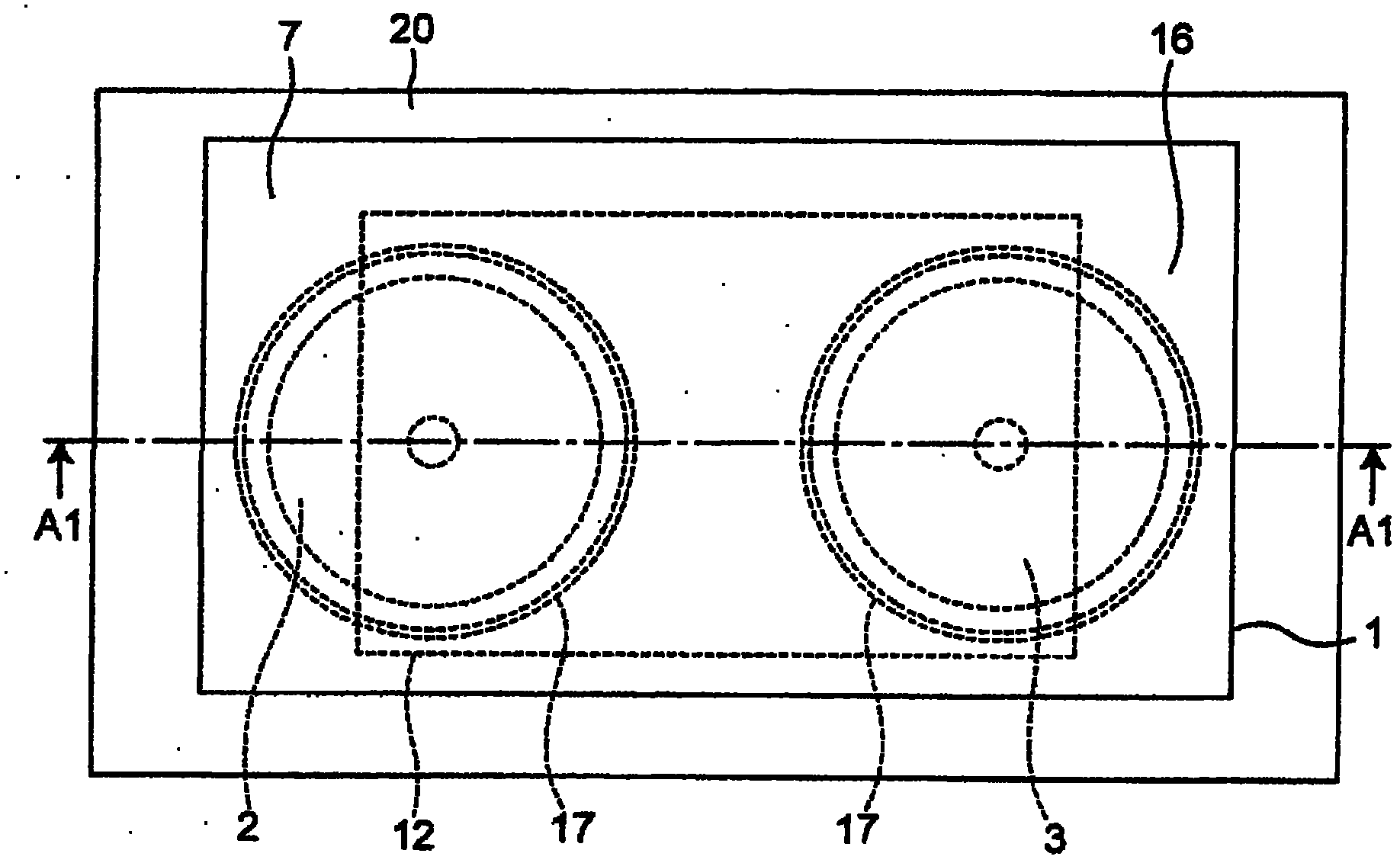
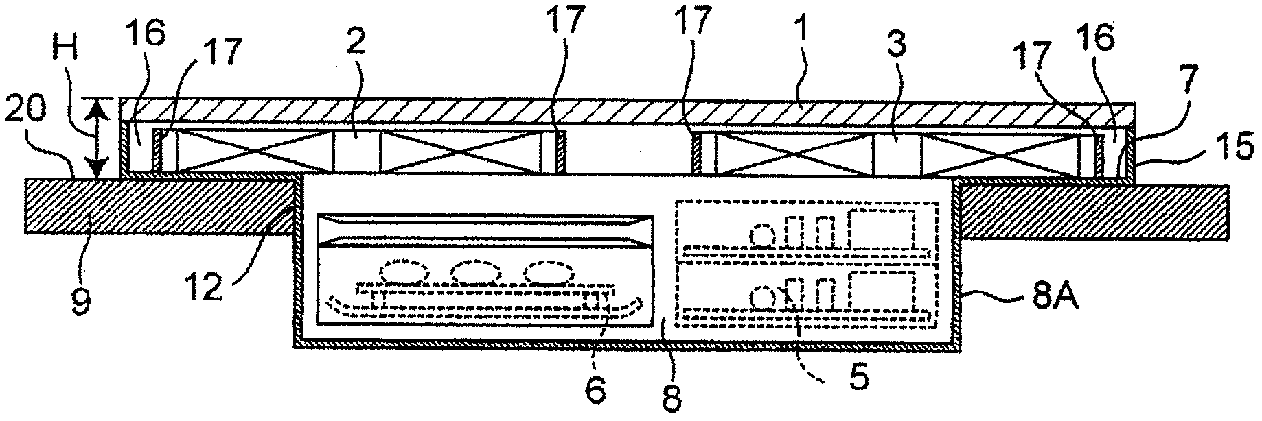
[0095] For the configuration of the induction heating cooker and the kitchen device equipped with the cooker according to the first embodiment of the present invention, Figure 1A and Figure 1B Be explained. Figure 1A It is a plan view of the kitchen apparatus equipped with the induction heating cooker which concerns on 1st Embodiment of this invention. Figure 1B yes Figure 1A A1-A1 line profile.
[0096] Such as Figure 1B As shown, the induction heating cooker of the first embodiment includes a casing 15 and a flat panel 1 made of a non-metal member such as heat-resistant glass covering the top of the casing 15 . The casing 15 has a box-shaped storage container 8A with an open upper portion, and a flange 7 extending on the outer peripheral side from the upper portion of the storage container 8A (so as to expand around in a substantially horizontal direction). The storage container 8A is a member that forms (partitions) the storage portion 8 that accommodates the inv...
no. 2 approach 》
[0119] Next, the configuration of the induction heating cooker according to the second embodiment of the present invention will be used Figure 4A and Figure 4B Be explained. Figure 4A It is a plan view of a kitchen device including an induction heating cooker according to a second embodiment of the present invention. Figure 4B yes Figure 4AA2-A2 line profile. The difference between the induction heating cooker of the second embodiment and the induction heating cooker of the above-mentioned first embodiment is that it further includes a temperature detection sensor 10, which is an example of a temperature detection device for detecting the temperature of an object to be heated, and constitutes a heating coil. Both end portions 11 a and 11 b of the windings 2 and 3 are arranged in the housing portion 8 .
[0120] Temperature detection sensor 10 such as Figure 4B As shown, it is placed in contact with the back surface of the plate 1 so that the temperature of the objec...
no. 3 approach 》
[0126] Use for the configuration of the induction heating cooker of the third embodiment of the present invention Figure 5A and Figure 5B Be explained. Figure 5A It is a plan view of a kitchen device including an induction heating cooker according to a third embodiment of the present invention. Figure 5B yes Figure 5A A3-A3 line profile. The induction heating cooker of the third embodiment is different from the induction heating cooker of the above-mentioned first embodiment in that an aluminum plate or the like is arranged between the heating coil 2 and the flange 7 and between the heating coil 3 and the flange 7 . A non-magnetic metal plate (also referred to as an antimagnetic material) 13 with high electrical conductivity and low magnetic permeability.
[0127] Here, if the top plate 20 of the kitchen cabinet 9 is made of a magnetic material such as magnetic stainless steel, the top plate 20 may be inductively heated by the heating coils 2 and 3 above the flange 7 ...
PUM
 Abstract
Description
Claims
Application Information