Counting coin box

A piggy bank and counter technology, applied in the direction of counting mechanisms/items, money bags, wallets, etc., can solve the problem that it is difficult to know the number of coins in the piggy bank, and achieve the effects of easy promotion, simple structure, and low cost

Inactive Publication Date: 2011-06-01
SHANGHAI JINGAN NO 1 CENT PRIMARY SCHOOL
View PDF0 Cites 1 Cited by
  • Summary
  • Abstract
  • Description
  • Claims
  • Application Information

AI Technical Summary

Problems solved by technology

[0003] The purpose of the present invention is to provide a counting piggy bank ...

Method used


Image

  • Counting coin box
  • Counting coin box

Examples


Embodiment Construction

[0013] In order to make the technical means, creative features, goals and effects achieved by the present invention easy to understand, the present invention will be further described below in conjunction with specific illustrations.

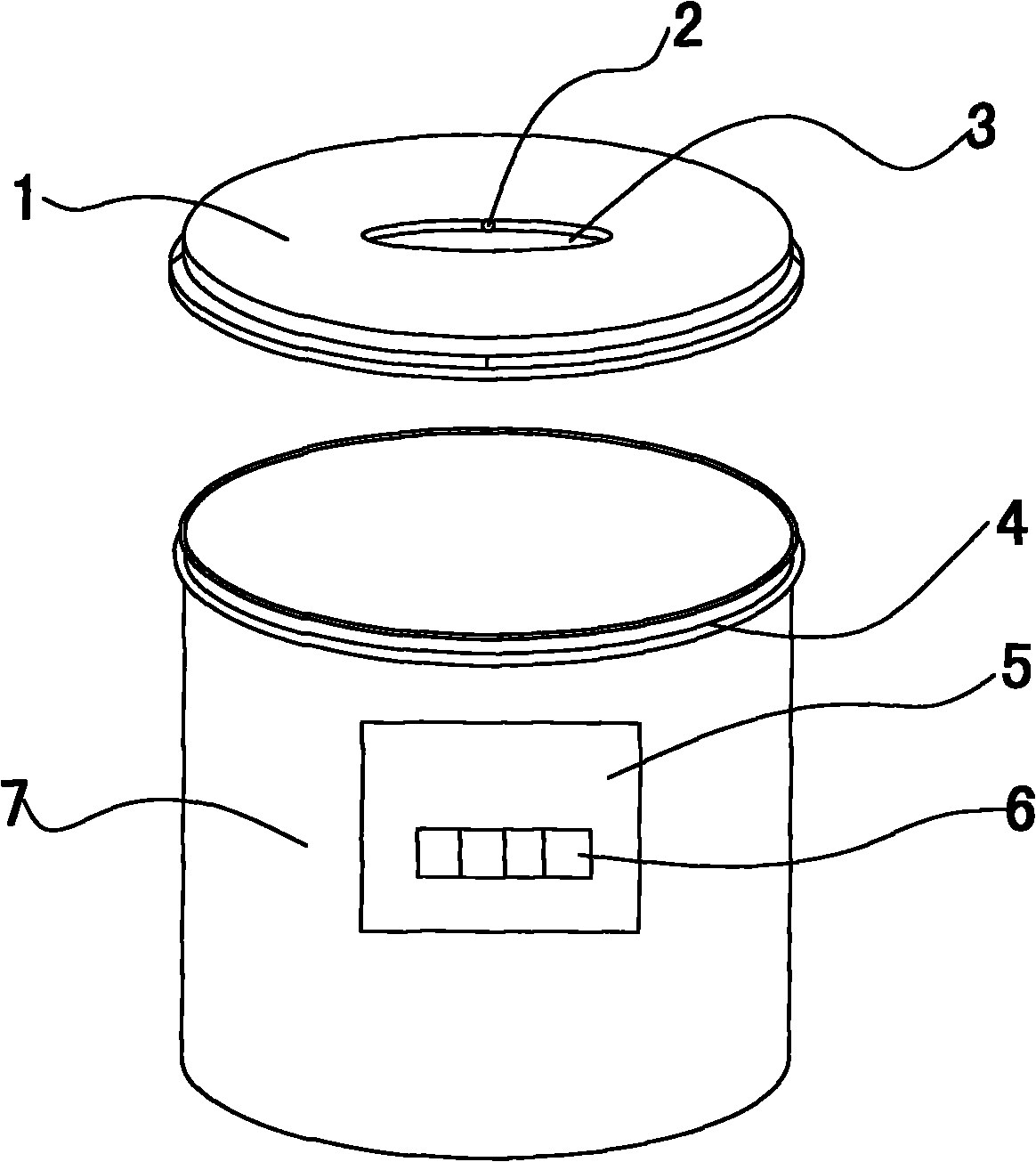
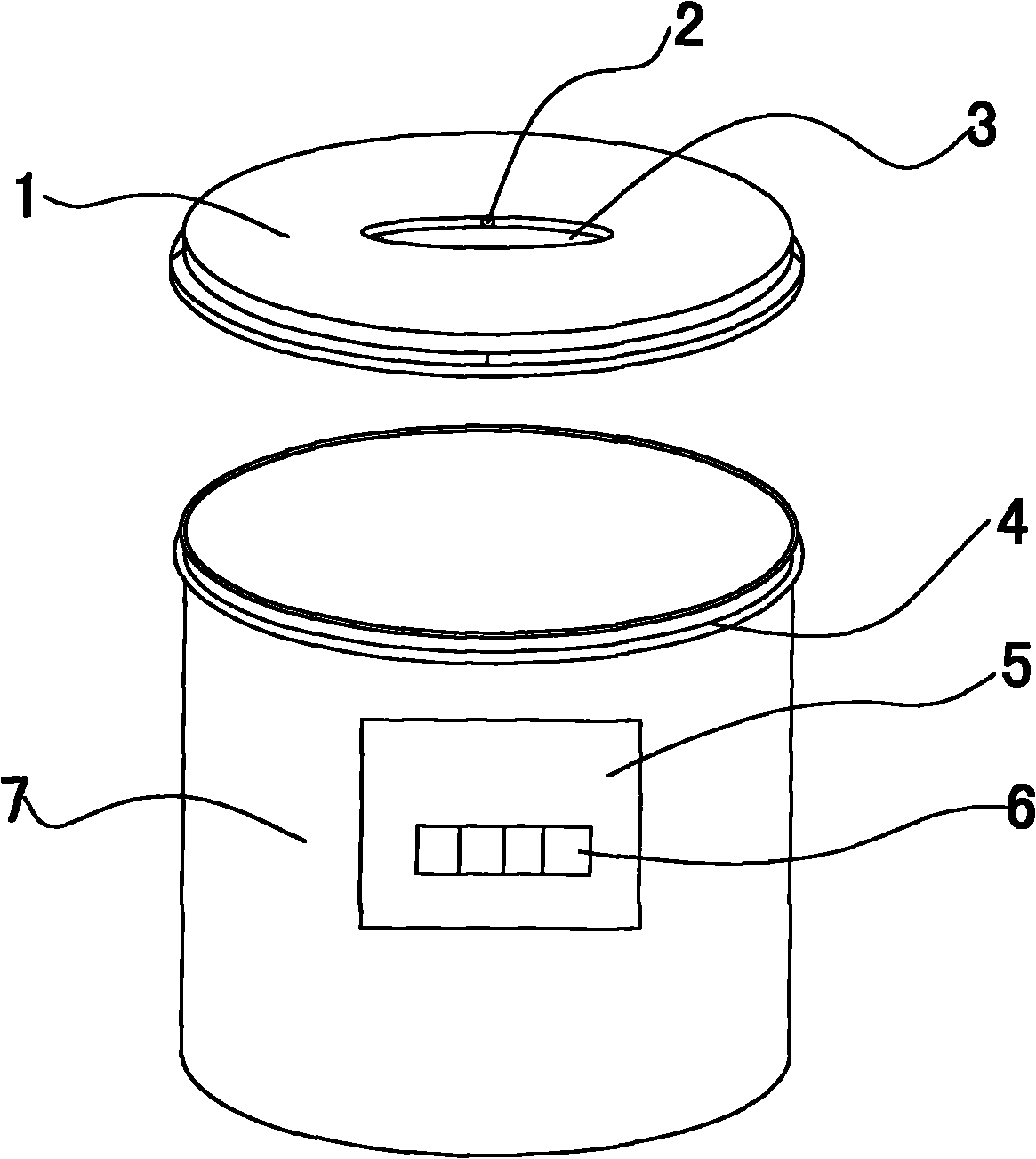
[0014] see figure 1 , a counting piggy bank, comprising a tank body 7 and a tank cover 1, the tank body 7 is cylindrical, with a diameter of 8cm and a height of 10cm. The top of the tank body 7 is provided with an external thread 4, and the bottom of the tank cover 1 is provided with an internal thread (not shown in the middle), and the tank body 7 and the tank cover 1 are screwed together.

[0015] An opening 3 is provided in the middle of the tank cover 1 for putting coins into the tank, and a grating sensor 2 is provided at the opening 3 .

[0016] A counter 5 is arranged on the front of the tank body, and a display screen 6 is arranged on the counter 5 . The grating sensor 2 on the can lid 1 is connected with the counter 5 .

[0017] The ...


PUM


Abstract

A counting coin box comprises a box body and a cover, wherein an opening is disposed on the cover for putting coins into the box. The counting coin box is characterized in that a grating sensor is disposed at the opening; a counter is disposed on the box body; the grating sensor is connected with the counter; and a display screen is disposed on the counter. The counting coin box has the advantage of counting function. The counting coin box has a simple structure and low cost, and is suitable for popularization.

Description

technical field [0001] The invention relates to a piggy bank, in particular to a piggy bank with a counting function. Background technique [0002] Piggy bank is mainly used to collect and store scattered coins. There are many types of piggy banks sold in the existing market, and piggy banks of various shapes and structures emerge in an endless stream to meet the requirements of consumers in general. However, there is no piggy bank with a counting function on the market, and the number of scattered coins in the piggy bank is unknown. Contents of the invention [0003] The object of the present invention is to provide a counting piggy bank to solve the problem that it is difficult to know the number of coins in the piggy bank. [0004] In order to achieve the above object, the technical scheme of the present invention is as follows: [0005] A counting piggy bank, comprising a tank body and a tank cover, the tank cover is provided with an opening for putting in coins, the...

Claims


Application Information

Patent Timeline
IPC IPC(8): A45C1/12G06M1/272
Inventor 赵文祺李娜
Owner SHANGHAI JINGAN NO 1 CENT PRIMARY SCHOOL
Why Eureka
Try Eureka