High efficiency air filter

A high-efficiency air and filter technology, used in suction filters, dispersed particle filtration, chemical instruments and methods, etc., can solve the problems of affecting the suction power of the machine, ejecting dust and falling to the ground, and inconvenient for customers to use, to increase dust storage. Space, reduce the suction rate and reduce the effect of convenient operation

Inactive Publication Date: 2011-06-01
LG ELECTRONICS (TIANJIN) APPLIANCES CO LTD
View PDF0 Cites 2 Cited by
  • Summary
  • Abstract
  • Description
  • Claims
  • Application Information

AI Technical Summary

Problems solved by technology

[0009] Most of the filters in the prior art use porous materials to filter the dust in the airflow. With the accumulation of dust in the filter material, the flow channel at the air inlet will be blocked, which will seriously affect the suction power of the machine, so it is necessary to Frequent cleaning or replacement of high-efficiency air filters will cause inconvenience to customers
[0010] The interference snap fit between the front cover and the back cover of the filter requires force to separate the front cover and the back cover when the filter needs to be cleaned and separated, which makes it easy for dust to pop up and fall to the ground when it is opened forcefully , causing secondary pollution

Method used


Image

  • High efficiency air filter
  • High efficiency air filter
  • High efficiency air filter

Examples


Embodiment Construction

[0027] Below in conjunction with accompanying drawing and specific embodiment the present invention is described in further detail:

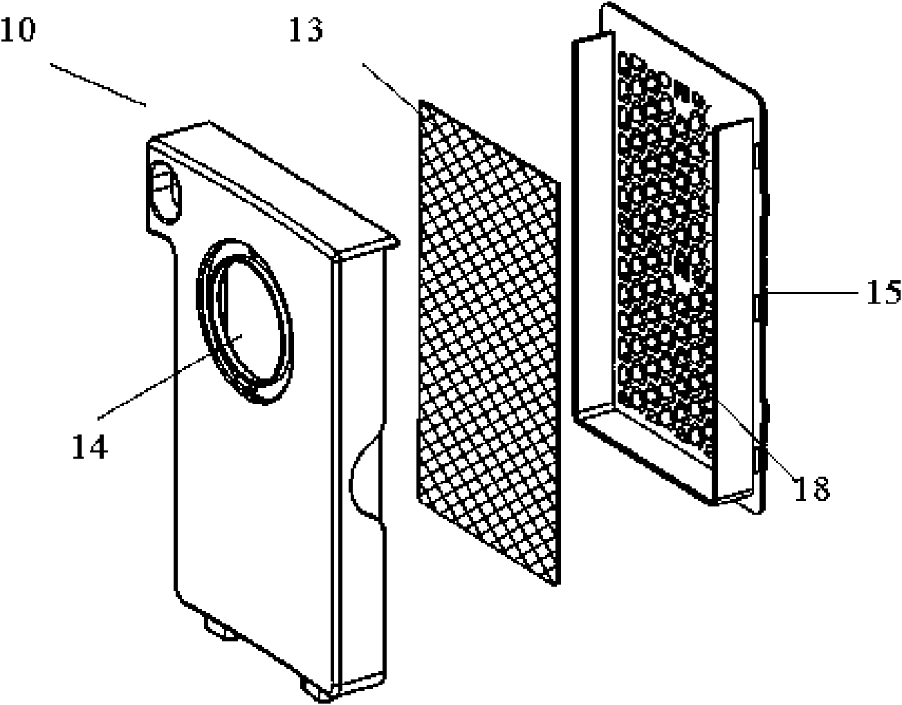
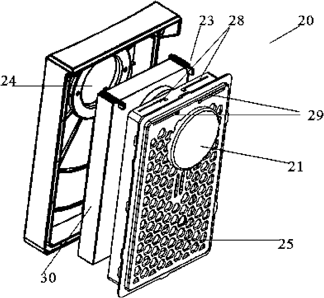
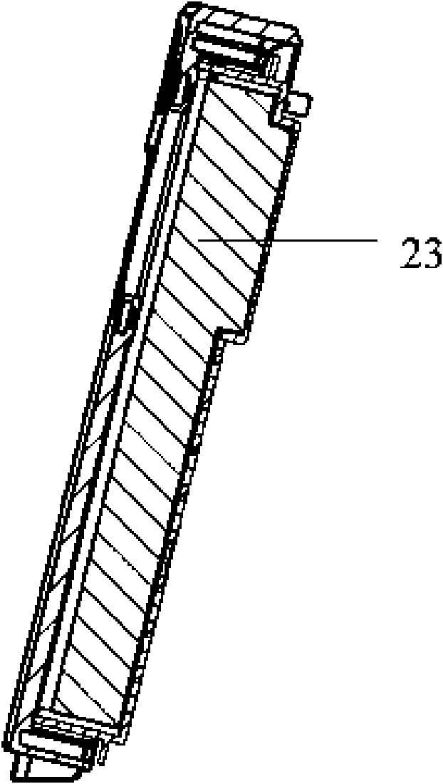
[0028] Such as Figure 2-6 As shown, the high-efficiency air filter 20 of the present invention is a box structure, and the box body is divided into two parts: a front cover, which includes a front panel and side walls, a top plate and a bottom plate forming four sides on the same side; a rear cover, It includes a grid 25, and fixedly formed on the same side of the side wall, top plate and bottom plate, the side wall on the grid 25 just can be inserted into the space limited by the side wall of the front panel to realize the front cover and Snap-fit ​​connection for the back cover. The grid 25 protrudes outwards corresponding to the air inlet to form a cylindrical buffer chamber, the buffer chamber is a bottom plate 21 relative to the air inlet, and the side wall 22 of the buffer chamber is made of a dense filter screen. Part of the airflow mi...


PUM


Abstract

The invention discloses a high efficiency air filter which is in a box-shaped structure and is characterized in that an air inlet is formed on a front wall plate, a rear cover grid is provided with an exhaust hole and is internally provided with a filtering material, a buffer cavity is formed in an externally convex manner on the grid corresponding to the air inlet, and two sides of the top of the grid are symmetrically provided with transverse guide slots; the filtering material is fixedly connected with a sheet which is fixedly connected with one end of a brake arm, a free end of the brake arm stretches to the outer side of the rear cover grid through the guide slots, and the brake arm can slide inside the guide slots. The grid is provided with the convex buffer cavity which can shunt the incoming flow, and simultaneously, a structure for manually shaking the filtering material is arranged, so the residual dust in sponge can be shaken off by manual compression and vibration, a matching structure for a guide plate and a positioning guide slot can connect a rear cover with a front cover so as to reduce the deformation of the front cover and the rear cover during engagement thereof, and with the help of the manual structure, a cover of the filter can be easily opened without dust falling; and the high efficiency air filter is simple in structure and convenient in operation, and enhances user satisfaction.

Description

technical field [0001] The invention relates to a vacuum cleaner, in particular to a high-efficiency air filter. Background technique [0002] Generally, a vacuum cleaner is a device that uses a vacuum to generate suction to inhale air, make the air flow through various filters, filter foreign objects in the air, and clean the room. [0003] Generally speaking, a vacuum cleaner mainly includes a suction device and a suction pipeline. The suction device mainly formed by a motor and a fan is arranged in the body. The suction pipeline includes a suction head and a suction pipe. The suction head has a downward opening. The suction port communicates with the air inlet of the fan inside the body through the telescopic pipe and the flexible pipe of the suction pipe. When the vacuum cleaner is running, the motor drives the impeller of the fan to rotate at a high speed, exhausting the air in the vacuum cleaner, forming an instantaneous vacuum in the vacuum cleaner, and forming a rel...

Claims


Application Information

Patent Timeline
Patent Type & Authority Applications(China)
IPC IPC(8): B01D46/42B01D46/00A47L9/12
Inventor 肖宗亮
Owner LG ELECTRONICS (TIANJIN) APPLIANCES CO LTD
Why Eureka
Try Eureka