Isolated-type bridge pier anti-collision device

An anti-collision device and isolation technology, which is applied to road safety devices, roads, roads, etc., can solve the problems of simple construction process, simultaneous construction of bridges, and low energy dissipation performance, so as to increase the overall anti-collision performance , The anti-collision function is stable and reliable, and the effect of enhancing the energy dissipation effect

Active Publication Date: 2012-10-03
CHINA RAILWAY SEVENTH GRP CO LTD +1
View PDF0 Cites 0 Cited by
  • Summary
  • Abstract
  • Description
  • Claims
  • Application Information

AI Technical Summary

Problems solved by technology

[0003] At present there are various types of anti-collision facilities for bridge piers in the world, and each anti-collision measure has its own characteristics and conditions of use, mainly including: 1. buffer material method; 2. buffer facility engineering method; 3. gravity method; 4. pile group method; 5. Artificial island method; 6. Thin shell cofferdam method; 7. Floating system mooring method; Maintenance-free, easy to repair after damage, no obstruction to navigation, can be built at the same time as the bridge, and can play a role during construction
For example, the floating composite pier energy dissipation and anti-collision combination device disclosed by the Chinese Patent Office on September 23, 2009 is a device that uses floating bodies for energy dissipation and anti-collision. It has a complex structure and high cost; at the same time, the energy dissipation performance is not high. , and can not be constructed at the same time as bridge construction; another example is a bridge anti-collision device disclosed by the Chinese Patent Office on July 9, 2008, which uses buffer facilities for energy dissipation, which requires the use of a large number of steel structures, and the cost high, and cannot be built at the same time as the bridge

Method used


Image

  • Isolated-type bridge pier anti-collision device
  • Isolated-type bridge pier anti-collision device
  • Isolated-type bridge pier anti-collision device

Examples


Embodiment Construction

[0029] Below in conjunction with accompanying drawing and embodiment the present invention will be further described:

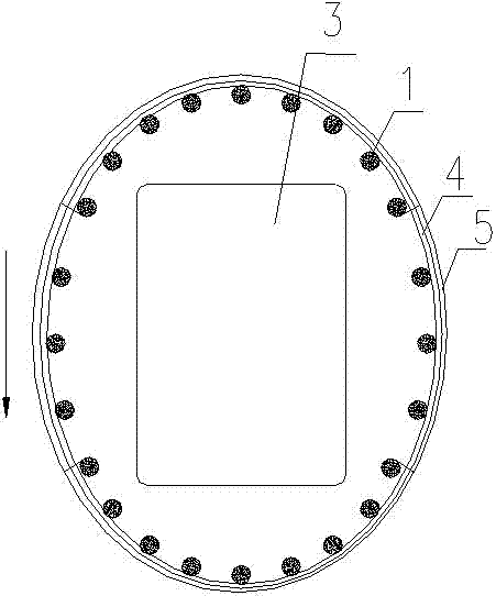
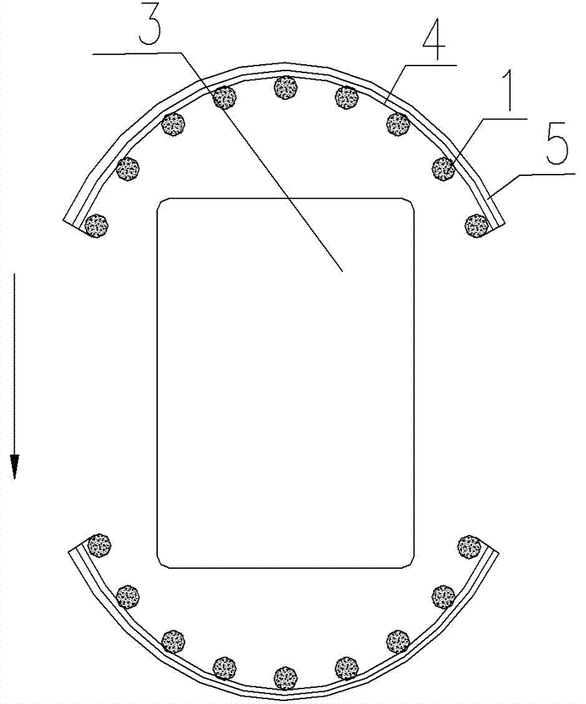
[0030] see figure 1 , embodiment 1 of the isolation type bridge pier anti-collision device of the present invention, it comprises arc surface anti-collision fairing 5 around pier 3, a plurality of protection piles 1, energy dissipation framework 4, and each protection pile 1 is arranged in arc shape around pier 3; A plurality of annular rubber rings 2 are sheathed on the protective piles 1 respectively, and the anti-collision fairing 5 is fixedly arranged on the protective piles 1 through the annular rubber rings 2 . Each protective pile 1 is arranged in an elliptical circular arc around the pier 3; the anti-collision fairing 5 is an elliptical cylinder, and the long axis direction of the ellipse is the direction of water flow.

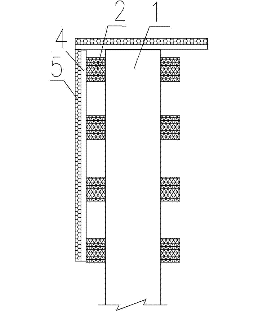
[0031] see figure 2 The energy dissipation frame 4 is arranged between the anti-collision fairing 5 and the annular rubber ring ...


PUM


Abstract

The invention provides an isolated-type bridge pier anti-collision device which comprises an arc surface anti-collision fairing surrounding the bridge piers and a plurality of protective piles, and each protective pile is arranged surrounding the bridge piers in an arc shape; and each protective pile is respectively sleeved with an annular rubber ring, and the anti-collision fairing is fixedly arranged on each protective pile through the annular rubber ring. The isolated-type bridge pier anti-collision device has the advantages of simple structure and principle, low cost, stable and reliable anti-collision function, long service life of anti-collision facilities, the annular rubber ring can effectively absorb the collision kinetic energy through the greater elastic deformation of the annular rubber ring, and can also rotate surrounding the protective piles when being collided to change the direction of the collision force; and the anti-collision fairing has the fairing function, and also can connect the plurality of protective piles, and the integral anti-collision performance of the protective piles is increased.

Description

technical field [0001] The invention relates to a bridge pier protection device, in particular to a bridge pier anti-collision device. Background technique [0002] With the development of land transportation, there are more and more bridges across rivers and seas, and bridge piers standing in the water have become obstacles to navigable waters. The accidents of ships colliding with bridge piers are increasing, which not only cause damage and damage to bridge piers, but also cause large bridges to collapse due to ship collisions, and ships will also be damaged as a result, or the waterway will be blocked due to ship sinking, affecting land and water traffic. damage to the environment. In order to ensure land and water traffic, it is necessary to study the mechanism of ships colliding with bridge piers, set up bridge anti-collision facilities, and prevent accidents of ships colliding with bridge piers. [0003] At present there are various types of anti-collision facilities...

Claims


Application Information

Patent Timeline
Patent Type & Authority Patents(China)
IPC IPC(8): E01F15/14
Inventor 方竞赖国甫易柏华方宇翔
Owner CHINA RAILWAY SEVENTH GRP CO LTD
Why Eureka
Try Eureka