
a range hood

A technology for range hoods and fans, which is applied in the direction of removing oil fume, mechanical equipment, machines/engines, etc., and can solve problems such as inability to achieve sealing effect, pollution of parts, and simplicity

Active Publication Date: 2015-11-25
BSH ELECTRICAL APPLIANCES JIANGSU
View PDF7 Cites 0 Cited by
  • Summary
  • Abstract
  • Description
  • Claims
  • Application Information

AI Technical Summary

Problems solved by technology

However, on the existing range hood, there is no special structural design about sealing at the joint between the air inlet of the volute casing and the base of the air inlet pipe, or the structure is too simple to achieve good sealing. As a result, the oil stains accumulated on the inner pipe wall here leak out from there. In many cases, the leaked oil stains will continue to spread downward along the outer surface of the parts in contact with it, causing these parts It is polluted, and sometimes even causes oil dripping in the gap between the shell walls of the range hood, which needs to be improved

Method used


Image

  • a range hood
  • a range hood
  • a range hood

Examples


Embodiment Construction

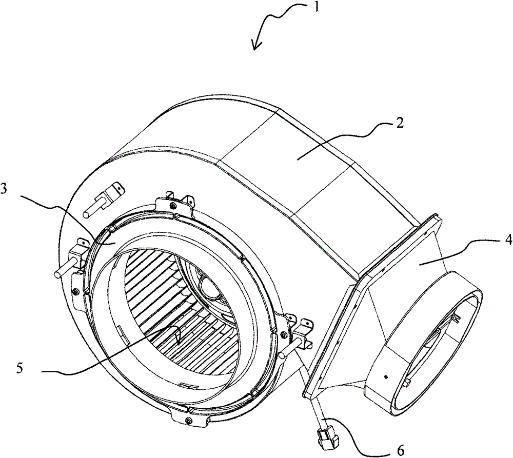
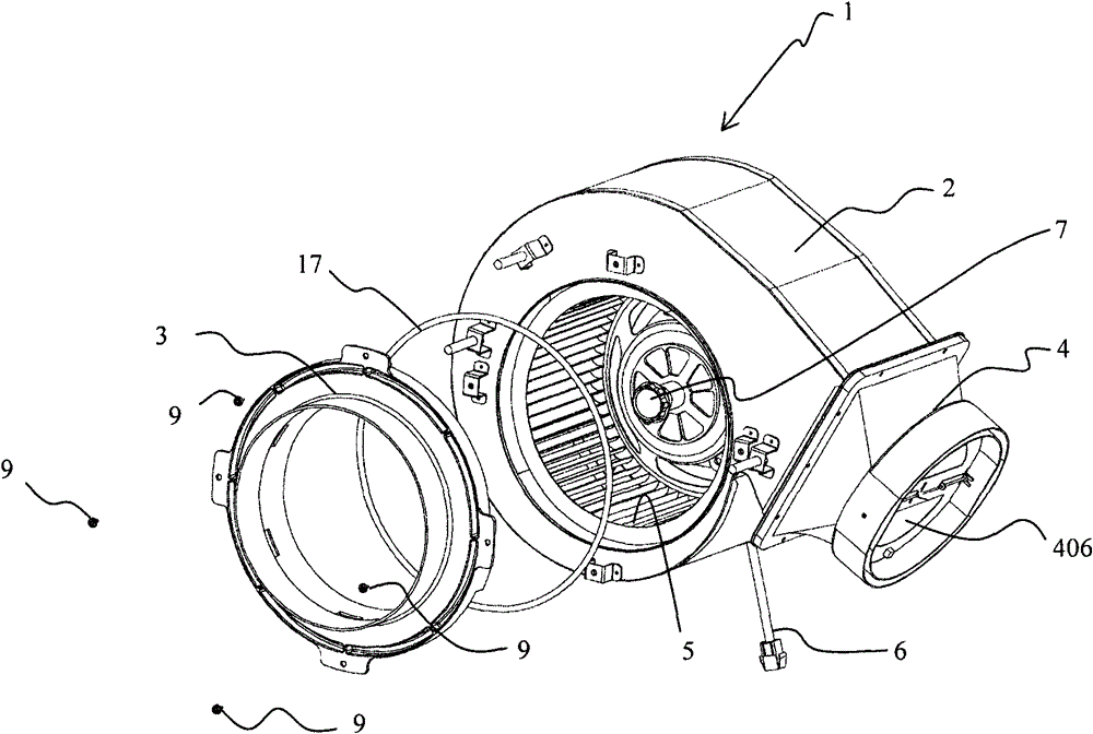
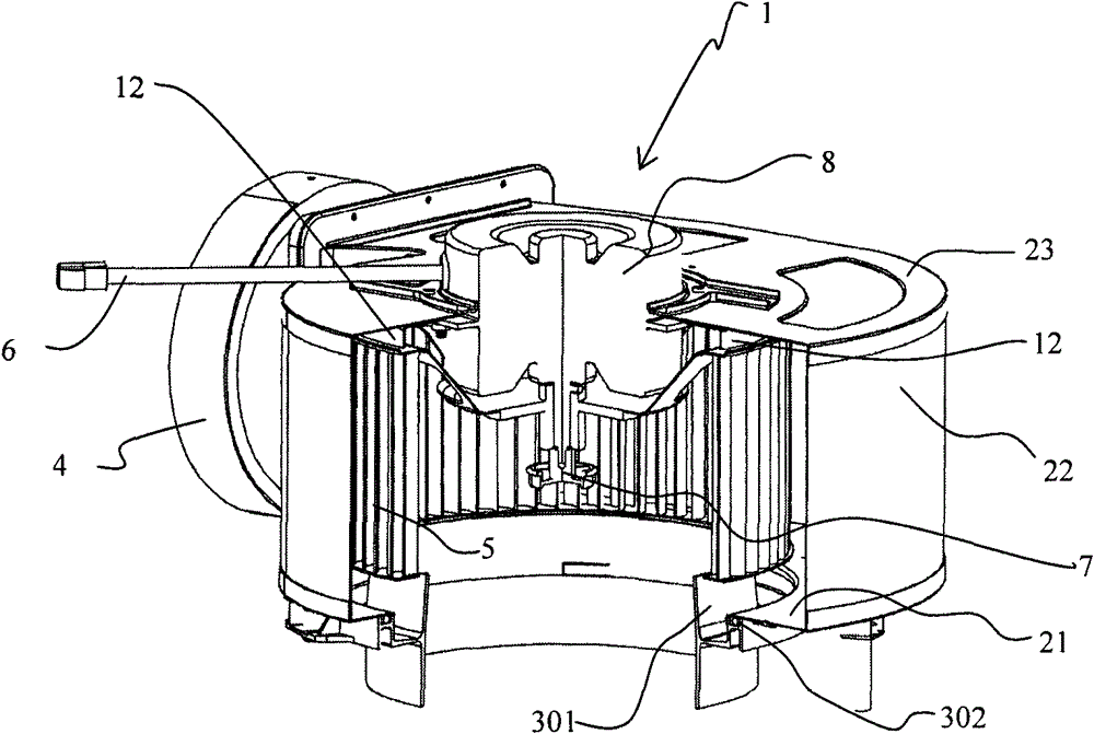
[0017] See attached Figures 1 to 5 , a range hood of the present invention, which is not shown in the figure, includes a fan system 1 that provides operating airflow power for the entire range hood. The fan system 1 is connected to an external power source of the range hood through a power cord 6 to supply power to a motor 8 as a power source. See attached image 3 , a cross-sectional view of the fan system 1, the impeller 5 is driven by a motor 8 to generate an operating airflow. The impeller 5 and the motor 8 are connected together by bolts 7 . The fan system 1 also includes fan components for housing the impeller 5 . The blower component includes a volute casing 2 and an air inlet pipe base 3 connected thereto. A sealing ring 17 made of elastic material is arranged between the volute casing 2 and the air inlet pipe base 3 connected thereto. The air inlet pipe base 3 has an air outlet end, and a sealing ring receiving groove 302 is arranged on the air outlet end. The ...


PUM


Abstract

The invention relates to a cooking fume exhauster, comprising a fan system (1). The fan system generally comprises a motor (8) acting as a power source, an impeller (5) driven by the motor and used for generating operational airflow and a fan component for accommodating the impeller, wherein the fan component comprises a volute-shaped casing (2) and an air inlet pipe base (3) connected therewith and further comprises a seal ring (17) made of elastic material, and the air inlet pipe base is provided with an air outlet end on which a seal ring accommodating groove (302) is arranged. The cooking fume exhauster adopting the technical scheme avoids the occurrence of oil dripping and leakage at the junction of the volute-shaped casing and the air inlet pipe.

Description

technical field [0001] The invention relates to a kitchen appliance, in particular to an island type range hood. Background technique [0002] A traditional range hood includes a fan system, which generally includes a motor as a power source, an impeller driven by the motor to generate a running airflow, and a fan part for containing the impeller, and the fan part includes a volute Shaped housing, the air inlet pipe base connected to its air inlet and the air outlet pipe base connected to its air outlet, through the air outlet pipe connected to the air outlet pipe base, the oily fume generated during the cooking process is discharged out of the kitchen . However, on the existing range hood, there is no special structural design about sealing at the joint between the air inlet of the volute casing and the base of the air inlet pipe, or the structure is too simple to achieve good sealing. As a result, the oil stains accumulated on the inner pipe wall here leak out from there...

Claims


Application Information

Patent Timeline
Patent Type & Authority Patents(China)
IPC IPC(8): F24C15/20F04D29/42F04D29/08
Inventor 袁建雄刘民贵夏兆阳
Owner BSH ELECTRICAL APPLIANCES JIANGSU
Learn More