Conical centrifugal liquid ring dynamic seal device for super-gravity rotating bed

A high-gravity rotating bed and sealing device technology, applied in chemical/physical/physical-chemical mobile reactors, fractionation, etc., can solve problems such as poor sealing performance, serious air leakage, and inconvenient manufacturing, and achieve good structural sealing performance, The effect of convenient installation and simple structure

Inactive Publication Date: 2012-08-22
ZHEJIANG UNIV OF TECH
View PDF13 Cites 2 Cited by
  • Summary
  • Abstract
  • Description
  • Claims
  • Application Information

AI Technical Summary

Problems solved by technology

However, the high-gravity rotating bed belongs to high-speed dynamic equipment compared with static equipment such as towers. A gas dynamic sealing device needs to be installed between the upper end surface of the rotor and the inner wall of the upper cover of the casing to prevent gas leakage and short circuit, thereby reducing the transmission rate of the rotating bed. Quality efficiency
At present, the gas dynamic seal of the high gravity rotating bed mainly adopts the labyrinth seal patent number 200910066851.5, the mechanical seal patent number 200310103434.6, the patent number 01143459.7, the centrifugal liquid ring seal patent number 95214611.8, the patent number 95107423, the patent number 200410073624.2, the patent number 02228172.8, the patent number 2020 , Stuffing box sealing patent No. 200920217341.9, these gas dynamic seals or poor sealing performance lead to serious air leakage, or complex structures, inconvenient manufacturing, or high wear and short life, which greatly affects the industrial application of high-gravity rotary beds

Method used


Image

  • Conical centrifugal liquid ring dynamic seal device for super-gravity rotating bed
  • Conical centrifugal liquid ring dynamic seal device for super-gravity rotating bed
  • Conical centrifugal liquid ring dynamic seal device for super-gravity rotating bed

Examples


Embodiment 1

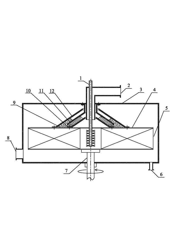
[0018] Embodiment 1: as figure 1 As shown, this conical centrifugal fluid ring dynamic sealing device for a supergravity rotating bed mainly includes a housing 3, a rotor 5, a rotating shaft 7, and a sealing device 17. The rotor 5 is fixed on the rotating shaft 7, and the housing 3 is sleeved on the rotor. 5 Externally, the upper part of the sealing device 17 is fixed on the inner wall of the upper part of the housing 3, and the lower part is fixed on the upper end surface 4 of the rotor 5, and is fixed by welding or fastening with bolts. The lower side of the housing 3 is provided with a gas phase inlet 8. The other side is provided with a liquid phase outlet 6, and the upper part of the housing 3 is provided with a liquid phase inlet 1 and a gas outlet 2.

[0019] The sealing device 17 mainly includes a movable outer conical disk 12, a static conical disk 11, a dynamic inner conical disk 10, a movable inner conical disk 10, a movable outer conical disk 12, a static conical d...

Embodiment 2

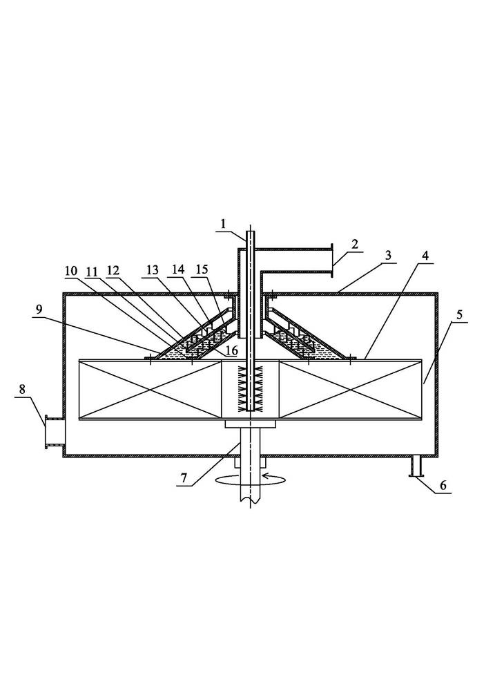
[0024] Embodiment 2: as figure 2 As shown, the difference with Embodiment 1 is that the upper and lower surfaces of the static conical ring 11 are provided with upper fins 13 and lower fins 15, and the upper surface of the movable inner conical ring 10 is provided with movable inner fins 16, and the movable inner conical ring 10 is provided with movable inner fins 16, The lower surface of the outer conical ring 12 is provided with movable outer fins 14, and the upper fins 13, lower fins 15, movable inner fins 16 and movable outer fins 14 are embedded with each other to reduce the dynamic sealing of the conical centrifugal fluid ring. Air leakage of device 17. The fins are welded vertical low circles, and the fins can be of various shapes and sizes.

Embodiment 3

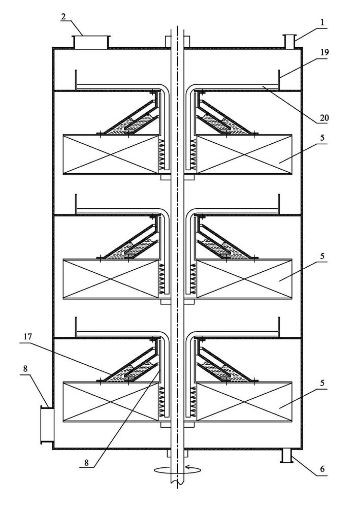
[0025] Embodiment 3: as image 3 As shown, there are multiple sets of rotors 5 and sealing devices 17 similar to Embodiment 1 or 2 connected in series on the rotating shaft 7. The center of the rotor 5 is provided with a riser pipe 18, and a drainage pipe 20 is provided near the rotating shaft 7. The upper port of the drainage pipe 20 is A cofferdam 19 is provided at the place.

[0026] Taking three rotors connected in series as an example, a sealing device 17 is installed on each of the upper end surfaces of the three rotors 5 . The gas enters the inner cavity of the rotating bed shell from the gas phase inlet 8, flows radially through the bottom rotor 5, enters the air riser 18 in the center of the rotor, flows upward, passes through the upper two rotors 5 in turn, and finally discharges from the gas outlet 2. The liquid enters from the liquid phase inlet 1, enters the uppermost rotor 5 through the cofferdam 19 and the drainage pipe 20, is thrown out under the action of cen...


PUM


Abstract

The invention relates to a conical centrifugal liquid ring dynamic seal device for a super-gravity rotating bed, which mainly comprises a casing, a rotor, a rotating shaft and a seal device. The rotor is fixed on the rotating shaft, the casing is sleeved outside the rotor, the upper portion of the seal device is fixed to the upper inner wall of the casing, the lower portion of the seal device is fixed to an upper end face of the rotor, a gas-phase inlet is arranged on one side of the lower portion of the casing, a liquid-phase outlet is arranged on the other side of the lower portion of the casing, and a liquid-phase inlet and a gas outlet are arranged on the upper portion of the casing. The conical centrifugal liquid ring dynamic seal device has excellent sealing performance, simple, compact and reasonable structure, low abrasion and long service life and is convenient to manufacture and process, and shutdown sealing is omitted during shutdown.

Description

technical field [0001] The invention relates to a conical centrifugal liquid circular dynamic sealing device, in particular to a conical centrifugal liquid circular dynamic sealing device for a supergravity rotating bed. Background technique [0002] The high-gravity rotating bed is a new high-efficiency gas-liquid mass transfer equipment developed in the 1970s. Inside the rotating bed is a high-speed rotating rotor whose centrifugal acceleration is hundreds to thousands of times that of gravity. Under the action of strong centrifugal force, the liquid forms an extremely thin liquid film and tiny droplets inside the rotor, and quickly flows to the outer edge of the rotor, while the gas flows to the inner edge of the rotor. The gas-liquid is in efficient countercurrent contact inside the rotor, the mass transfer coefficient and the gas-liquid contact specific surface area are greatly increased, and the mass transfer, heat transfer, gas-liquid reaction and micro-mixing proces...

Claims


Application Information

Patent Timeline
Patent Type & Authority Applications(China)
IPC IPC(8): B01J19/28B01D3/30
Inventor 计建炳李育敏敖翔
Owner ZHEJIANG UNIV OF TECH
Why Eureka
Try Eureka