Cast-in-place drainage channel structure of free-form construction top plate and construction method

A technology for drainage channels and roofs, which is applied to drainage structures, waterway systems, water supply devices, etc., can solve the problems of troublesome, impossible, and troublesome dismantling of bottom molds and supports, so as to save the dismantling work, improve work efficiency, and facilitate construction. Effect

Active Publication Date: 2017-07-07
ZHENGZHOU MUNICIPAL ENG CORP
View PDF10 Cites 2 Cited by
  • Summary
  • Abstract
  • Description
  • Claims
  • Application Information

AI Technical Summary

Problems solved by technology

[0005] However, compared with the traditional "prefabricated cover slab method" construction drainage process, the integral pouring drainage process is relatively troublesome. The integral pouring drainage process is generally The bottom formwork for pouring the top slab must be supported, and the bottom formwork must be supported. After the construction, the support and bottom formwork need to be removed. For small drainage channels, it is very troublesome to remove the bottom formwork and support after the top slab is poured can't even do

Method used


Image

  • Cast-in-place drainage channel structure of free-form construction top plate and construction method

Examples


Embodiment Construction

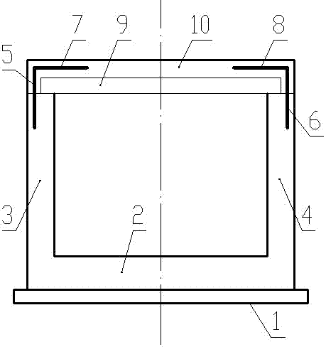
[0028] Such as figure 1 As shown, the cast-in-place drainage channel structure of the formless construction roof of the present invention includes a cushion 1, on which a bottom plate 2 is poured, and the left and right sides of the bottom 2 are respectively upwardly poured with a left wall 3 and a right wall 4. The top of the wall 3 is buried with a left connecting steel bar 5, and the top of the right wall 4 is buried with a right connecting steel bar 6; The top of the connecting steel bar 6 protrudes upwards from the right side wall 4 and bends to the left to provide a right horizontal part 8;

[0029] A plate-shaped top plate member 9 is placed between the tops of the left side wall 3 and the right side wall 4, the left end of the top plate member 9 is located in the middle of the upper surface of the left side wall 3, and the right end of the top plate member 9 is located on the right side wall 4. The middle position in the left-right direction of the upper surface;

[...


PUM


Abstract

The invention discloses a cast-in-place drainage channel structure of a free-form construction top plate. The cast-in-place drainage channel structure comprises a cushion layer, wherein a bottom plate is poured on the cushion layer; a left side wall and a right side wall are poured on the left side and the right side of the bottom plate separately; a left connecting rebar and a right connecting rebar are buried into the tops of the left side wall and the right side wall; a top plate member is arranged between the tops of the left side wall and the right side wall; and a top plate wrapping body is poured on the tops of the left side wall and the right side wall and on the top plate member. The invention further discloses a construction method of the cast-in-place drainage channel structure of the free-form construction top plate. The method comprises the steps of prefabricating the top plate member in batches; casting the cushion layer, the bottom plate, the left side wall and the right side wall on site; installing the top plate member; and casting the top plate wrapping body. The sealing property of a drainage channel can be ensured, the problem that a bottom form and a support used for casting the top plate in a traditional construction method are difficult to remove is solved, the construction efficiency is relatively high, and the proficiency requirement on filling operation of a worker is lower than that in a traditional ''cover plate method prefabricating method''.

Description

technical field [0001] The invention relates to the technical field of building construction, in particular to a construction structure and a construction method of a drainage channel. Background technique [0002] Modern urban diversion drainage systems are divided into sewage drainage systems and rainwater drainage systems, both of which are pressure-free systems. Sewage drainage systems are usually composed of pipes, and rainwater drainage systems are usually composed of pipes or drains. [0003] The second paragraph of Article 9.1.1 of the national standard "Code for Construction and Acceptance of Water Supply and Drainage Pipeline Engineering" 50268-2008 stipulates that the tightness test of the pipeline should be carried out for the non-pressure pipeline. However, there is no clear test requirement for the tightness of drains. With the frequent occurrence of extreme weather, many cities in China are frequently flooded. When flooding occurs, the rainwater system is over...

Claims


Application Information

Patent Timeline
Patent Type & Authority Applications(China)
IPC IPC(8): E03F5/00
CPCE03F5/00
Inventor 吴纪东王明远陈波光军伟代璐张双梅李永治李琪勇张强马国强焦锋王凌欣兰和彬许瑞峰刘建华李乐辉张标申鹏飞吕黎涛
Owner ZHENGZHOU MUNICIPAL ENG CORP
Why Eureka
Try Eureka