Thermal error compensation device on basis of numerical control workbench

A compensation device and workbench technology, applied in program control, computer control, general control system, etc., can solve the problem that the error compensation model is not robust and versatile enough, the anti-interference ability of the thermal error compensation device is decreased, and the temperature detection and Identifying problems such as time consumption, to achieve the effect of simple structure, improved anti-interference, and less interface occupation

Inactive Publication Date: 2011-06-01
UNIV OF ELECTRONICS SCI & TECH OF CHINA
View PDF4 Cites 8 Cited by
  • Summary
  • Abstract
  • Description
  • Claims
  • Application Information

AI Technical Summary

Problems solved by technology

This connection method has the following disadvantages: (1) First, because the temperature sensors of the existing thermal error compensation technology are arranged in parallel, each temperature sensor must be connected to the temperature acquisition controller through a separate connection, so many The wiring after each temperature sensor is connected to the temperature acquisition control unit is complicated
(2) Secondly, because the temperature sensor of the existing thermal error compensation technology uses analog data for transmission, the anti-interference ability of the thermal error compensation device is reduced, and the robustness and versatility of the error compensation model are not good enough; (3) Thirdly, because the existing thermal error compensation device is connected to the numerical control system through a serial port, and the parameters of the system are indirectly modified through the PLC module in the numerical control system, due to the slow data transmission speed of the serial port itself, and the temperature detection of the thermal error compensation device and identification time consumption, so that the compensation lags behind, and the compensation cannot be completed ideally

Method used


Image

  • Thermal error compensation device on basis of numerical control workbench
  • Thermal error compensation device on basis of numerical control workbench
  • Thermal error compensation device on basis of numerical control workbench

Examples


Embodiment 1

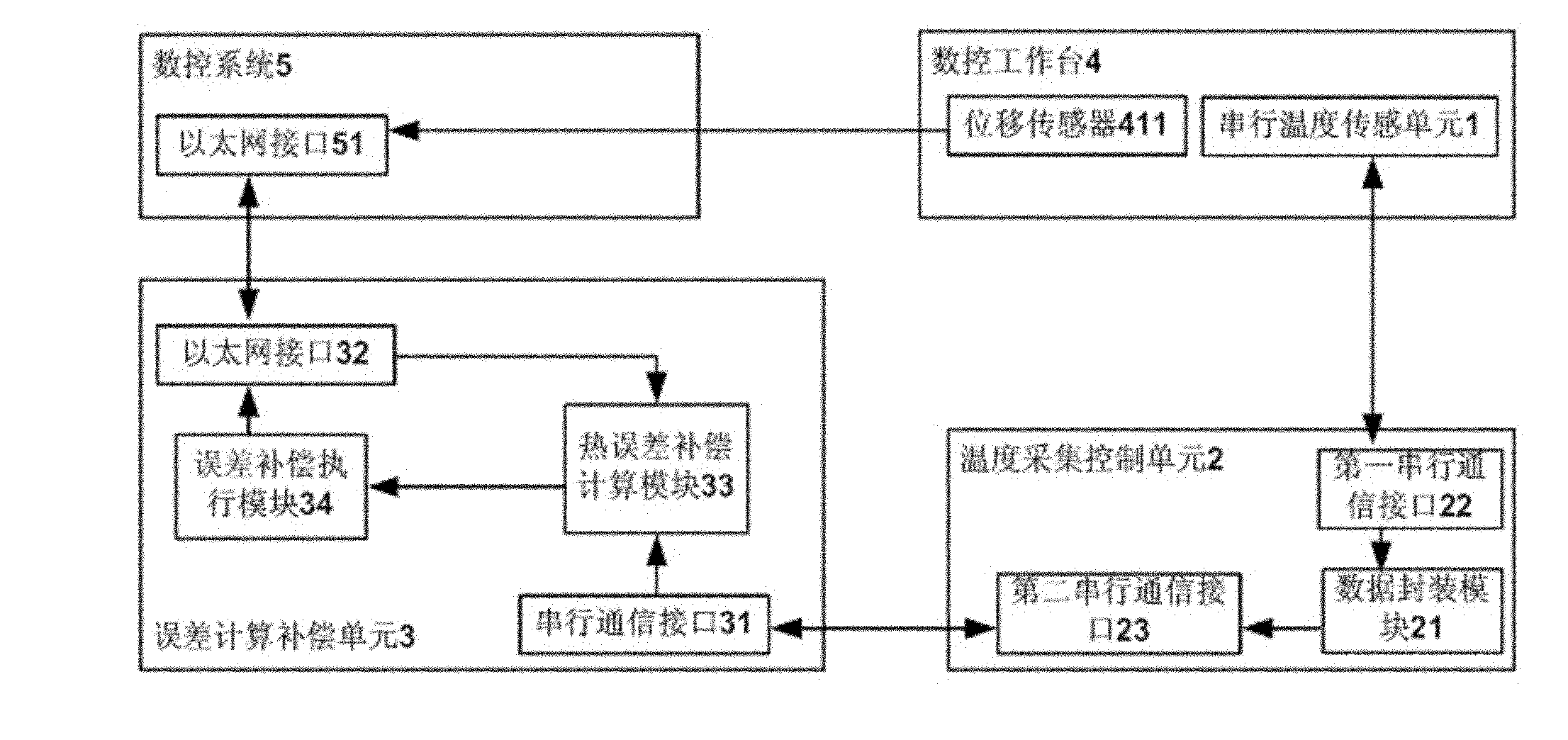
[0014] Embodiment 1: as figure 1 As shown, a thermal error compensation device based on a numerical control workbench includes a serial temperature sensing unit 1 distributed on a numerical control workbench 4, a temperature acquisition control unit 2 connected to the serial temperature sensing unit 1 and a temperature The error calculation and compensation unit 3 connected to the acquisition control unit 2, the temperature sensing unit 1 includes seven temperature sensors 14, and the temperature sensors 14 are connected in series to form a group and then connected to the temperature acquisition control unit 2, and are divided into digital quantities The temperature information is transmitted to the temperature acquisition control unit 2 respectively.

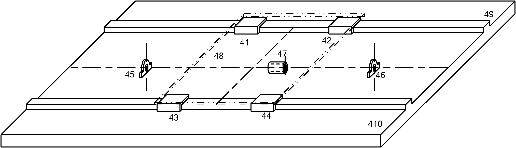
[0015] Such as figure 2 Shown is a kind of scene of concrete application of the present invention, among the figure numerical control workbench 4 comprises slide block 41,42,43,44, screw bearing 45,46, lead screw nut 47, work...

Embodiment 2

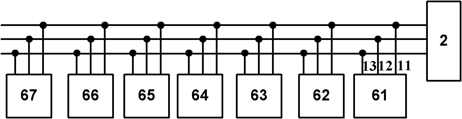
[0020] Embodiment 2: as Figure 4As shown, the difference between this embodiment and Embodiment 1 is that the temperature sensors 14 are connected into two groups and then connected through an adapter. In this embodiment, the first measurement and control point 61, the second measurement and control point 62, and the third measurement and control point 63 are connected into a group through a data bus, and then the fourth measurement and control point 64, the fifth measurement and control point 65, and the sixth measurement and control point 66 are connected through another group. One data bus is connected to the other group, and then the two groups of data buses are connected through the adapter 7, and finally connected to the controller. In this way, real-time control of multiple numerical control workbenches 4 can be realized through one temperature acquisition control unit 2 . The above-mentioned adapter 7 has an input connector, which includes three wire ends for connect...


PUM


Abstract

The invention relates to a thermal error compensation device on the basis of a numerical control workbench, which comprises serial temperature sensing units distributed on the numerical control workbench, a temperature acquisition control unit connected with the serial temperature sensing units and an error computing and compensating unit connected with the temperature acquisition control unit. The thermal error compensation device is characterized in that each temperature sensing unit comprises at least two temperature sensors; and the temperature sensors are connected with the temperature acquisition control unit after being connected in series into a group and respectively transfer temperature information of the temperature sensors to the temperature acquisition control unit in a digital quantity mode at different time. The thermal error compensation device has the beneficial effects of simple structure, convenience for connection, few occupied interfaces and the like.

Description

technical field [0001] The invention belongs to the technical field of thermal error compensation, in particular to the technical field of thermal error compensation of a numerical control workbench. Background technique [0002] With the development of precision and ultra-precision machining technology and the continuous improvement of the automation of machining and manufacturing, people put forward higher requirements for the machining accuracy of CNC workbench. A large number of studies have shown that thermal error has become the largest error source of CNC machining devices, so the control of thermal errors has become a key technology for high-precision CNC machining devices to improve machining accuracy. Now, we use many ways to reduce the thermal error of CNC machining devices, which can be roughly divided into two methods: error prevention method and error compensation method. The error prevention method relies on improving hardware such as improving the structural...

Claims


Application Information

Patent Timeline
Patent Type & Authority Applications(China)
IPC IPC(8): G05B19/404
Inventor 黄大贵吴献钢葛森余文正
Owner UNIV OF ELECTRONICS SCI & TECH OF CHINA
Why Eureka
Try Eureka