Method for distinguishing temperature of submersible motor based on lumped parameter model

A technology of centralized parameter model and submersible motor, which is applied in the direction of temperature measurement of moving solids, electrical digital data processing, special data processing applications, etc., can solve problems such as temperature information constraints, achieve small amount of calculation, realize soft measurement, high reliability effect

Active Publication Date: 2011-06-01
HARBIN INST OF TECH
View PDF0 Cites 9 Cited by
  • Summary
  • Abstract
  • Description
  • Claims
  • Application Information

AI Technical Summary

Problems solved by technology

[0004] The purpose of the present invention is to solve the problem that the temperature information of the submersible motor obtained by using a temperature sensor is restricted by the downhole environment, and to provide a temperature identification method for the submersible motor based on a centralized parameter model

Method used


Image

  • Method for distinguishing temperature of submersible motor based on lumped parameter model
  • Method for distinguishing temperature of submersible motor based on lumped parameter model
  • Method for distinguishing temperature of submersible motor based on lumped parameter model

Examples


specific Embodiment approach 1

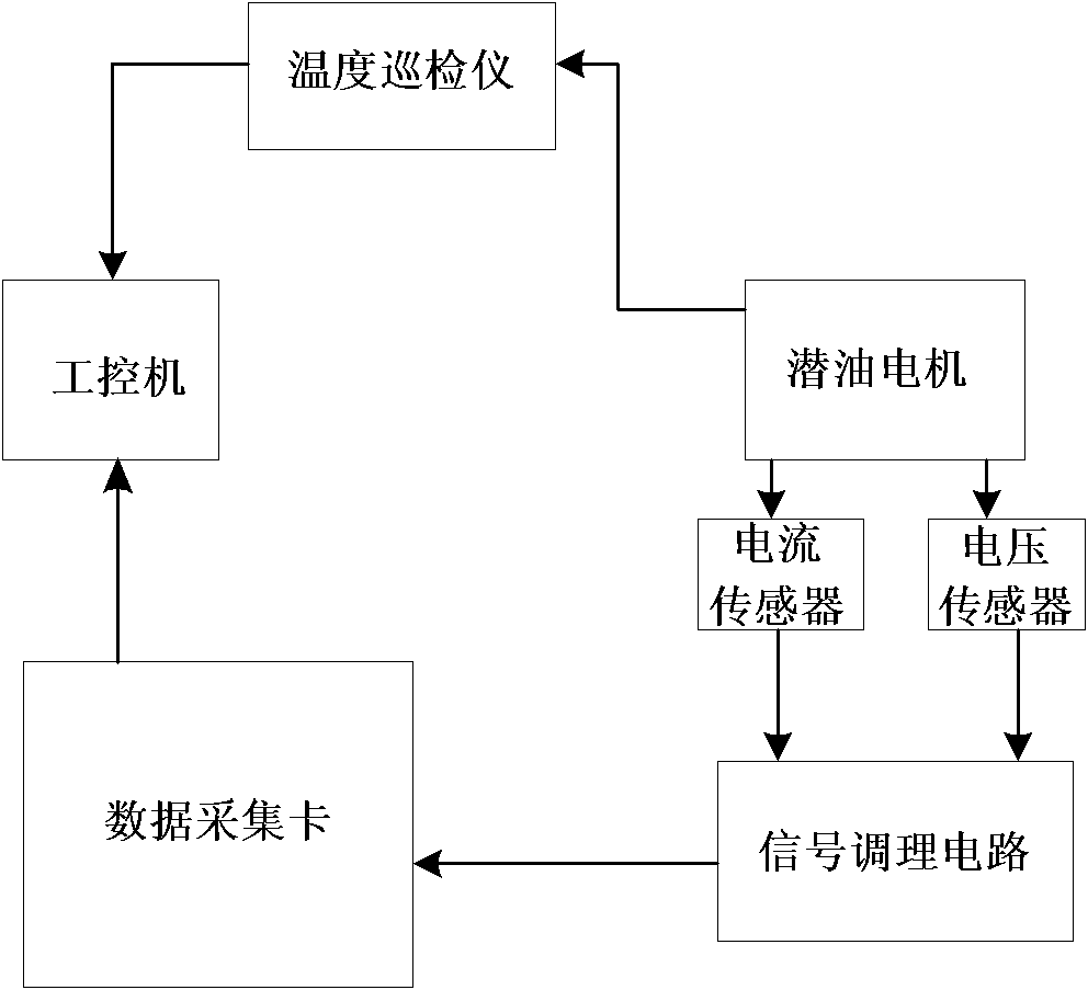
[0029] Specific implementation mode 1: the following combination Figure 1 to Figure 13 To describe this embodiment, this embodiment includes the following steps:

[0030] Step 1: Collect the three-phase stator voltage and the three-phase stator current of the submersible motor;

[0031] Step 2: Process the three-phase stator voltage and the three-phase stator current separately through the signal conditioning circuit, and use the processed signals as the stator original current input signal and the stator original voltage input signal;

[0032] Step 3: Use an industrial computer to calculate the total heating value u of the submersible motor based on the original stator current input signal and the stator original voltage input signal;

[0033] Step 4: In the industrial control computer, the total heating value u of the submersible motor is distributed to the components of the submersible motor according to the geometric size and energy consumption ratio of the components in the subme...

specific Embodiment approach 2

[0042] Specific implementation manner 2: the following combination Picture 12 with Figure 13 To explain this embodiment, this embodiment is a further explanation of the first embodiment. In step 3, the method for calculating the total heating value u of the submersible motor based on the stator original current input signal and the stator original voltage input signal using an industrial control computer is: The total heating value u of the submersible motor is the iron loss W i , Stator copper loss W s And rotor copper loss W r And the expression is u=W i +W s +W r ,

[0043] W i = [ 1 cR m - R d c X m ( X m + 2 x sc ) ] V p 2 - [ 1 - cX m X m + 2 x sc ] R d I p 2 ,

[0044] W s = R d I p 2 ,

[0045] W r = - R z X m ( X m + 2 x sc ) V p 2 + c 2 X m ...

specific Embodiment approach 3

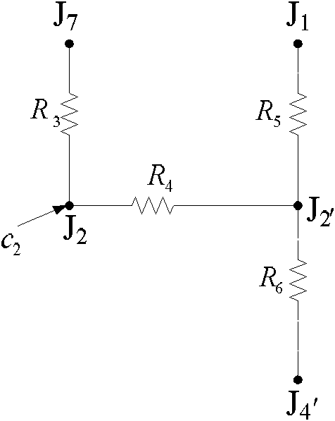
[0050] Specific implementation manner three: the following combination Figure 2 to Figure 11 This embodiment is described. This embodiment is a further description of the second embodiment. The equivalent circuit of each component of the submersible motor in step 4 is to simulate and calculate the thermal convection and thermal contact resistance of each component.

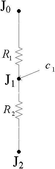
[0051] 41): Calculate the thermal contact resistance of the base as resistance R 1 And R 2 Resistance network, where the resistance R 1 And R 2 In series at node J 0 And J 2 Between, R 1 And R 2 The connection point is node J 1 , R 1 For direct measurement,

[0052] R 2 = 1 πh c Lr 1 ,

[0053] Where h c Is the contact coefficient between the base and the iron core, L is the length of the stator, r 1 Is the outer diameter of the stator;

[0054] Simulate the thermal convection of the base as c 1 :

[0055] c 1 = M e c e + 1 2 M f c f ,

[0056] Wh...


PUM


Abstract

The invention provides a method for distinguishing the temperature of a submersible motor based on a lumped parameter model, belonging to the technical field of an application base of combination of thermodynamics modeling and motor control. The method is used for solving the problem that acquisition of temperature information for the submersible motor by using a temperature sensor is restricted by subsurface environments. The method comprises the following steps: firstly, collecting the three-phase stator voltage and three-phase stator current of the submersible motor; then, respectively processing the three-phase stator voltage and the three-phase stator current by a signal conditioning circuit, wherein the processed signals as original current input signals of a stator and original voltage input signals of the stator; calculating the gross calorific power u of the submersible motor by an industrial personal computer (IPC) in accordance with the original current input signals of the stator and the original voltage input signals of the stator; and allocating the gross calorific power u to each part of the submersible motor, combining equivalent circuits of the submersible motor, constructing a lumped parameter heat network model and solving the lumped parameter heat network model to obtain a temperature value of each part of the submersible motor. The method is applied to distinguishing the temperature of the submersible motor.

Description

Technical field [0001] The invention relates to a method for identifying the temperature of a submersible motor based on a lumped parameter model, and belongs to the basic technical field of application combining thermodynamic modeling and motor control. Background technique [0002] Submersible motors generally work at a depth of 1.0~3.5km underground and are connected to the ground power supply through armored cables. The underground environment temperature is as high as 120℃. When the motor works in the well, it will inevitably generate a certain amount of heat to cause the motor to generate heat. When the centrifugal pump is discharged, it will take away heat to make the motor dissipate, so that the temperature rise of the motor will not exceed a certain limit, otherwise the motor will be burned due to excessive temperature rise. In order to ensure its safe, efficient and stable operation, it is necessary to monitor the temperature changes of the submersible motor downhole to...

Claims


Application Information

Patent Timeline
Patent Type & Authority Applications(China)
IPC IPC(8): G06F17/50G01K13/04
CPCY02T10/82
Inventor 王立国徐殿国张凤娜李临春郝宏海任翔夏禹吕琳琳董明轩
Owner HARBIN INST OF TECH
Why Eureka
Try Eureka