
Film coating device

A coating device and sputtering technology, applied in sputtering coating, ion implantation coating, vacuum evaporation coating and other directions, can solve the problems of voltage instability and affect product quality, and achieve the effect of voltage stability

Inactive Publication Date: 2011-06-08
HONG FU JIN PRECISION IND (SHENZHEN) CO LTD +1
View PDF4 Cites 3 Cited by
  • Summary
  • Abstract
  • Description
  • Claims
  • Application Information

AI Technical Summary

Problems solved by technology

The driving mechanism includes motors, multiple gear modules and other components. Therefore, there are many transmission components through which the current is transmitted, and the path of voltage transmission is long. However, the components rotate and contact each other, resulting in unstable input voltage and affecting product quality.

Method used


Image

  • Film coating device
  • Film coating device
  • Film coating device

Examples


Embodiment Construction

[0009] The present invention will be further described in detail below in conjunction with the accompanying drawings.

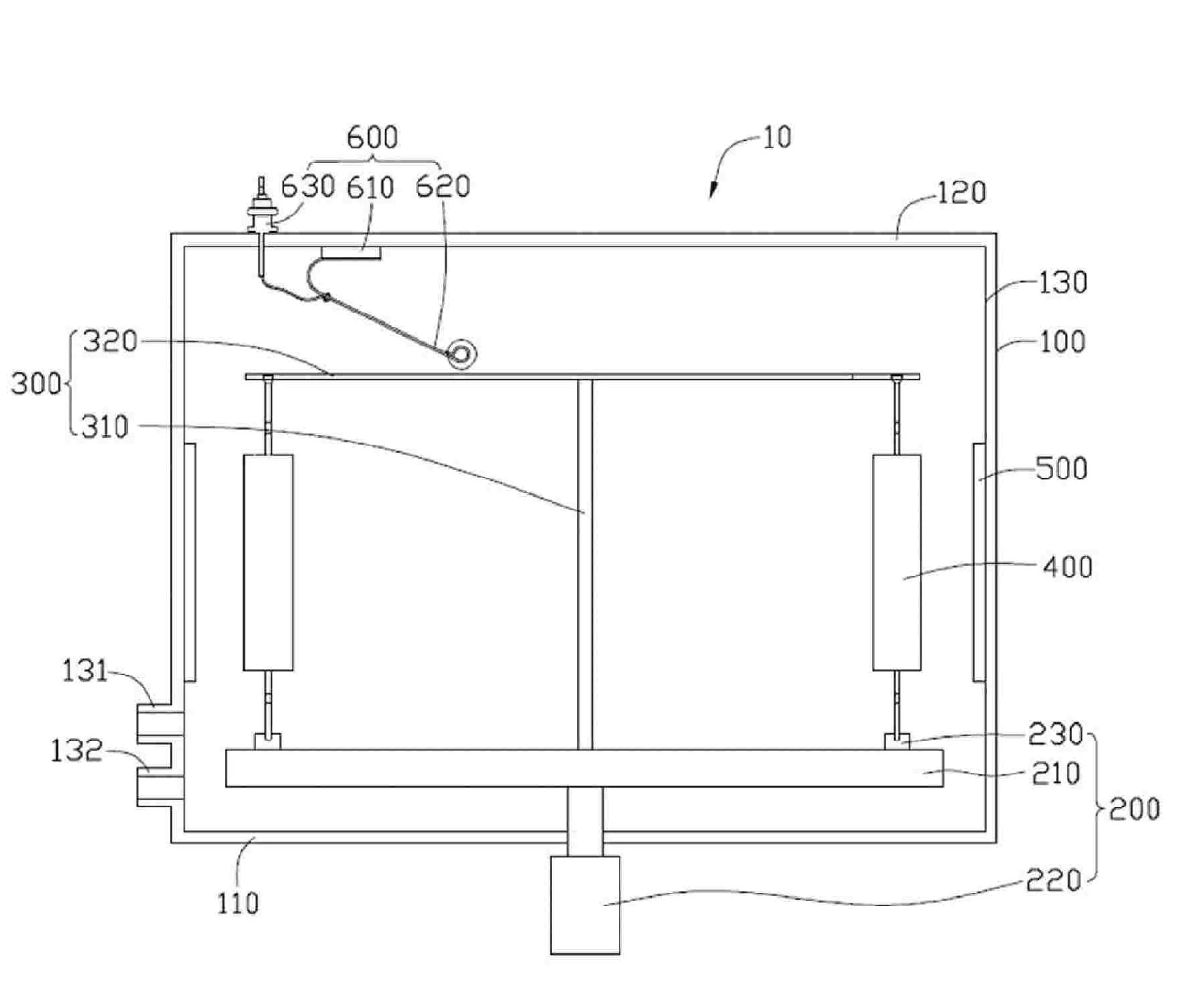
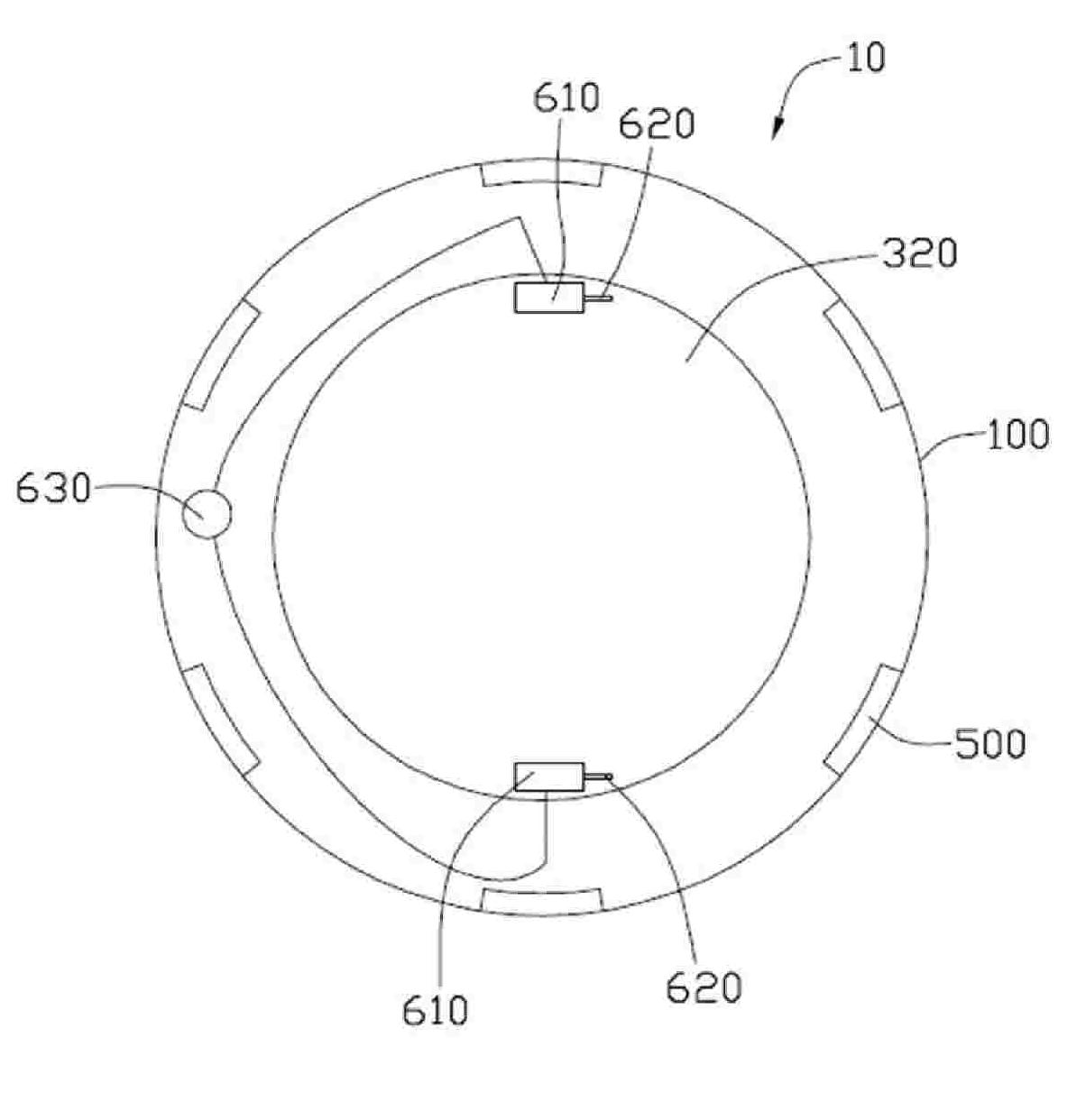
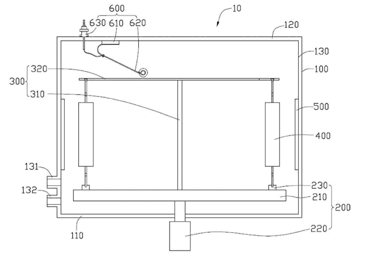
[0010] see figure 1 as well as figure 2 , a coating device 10 provided by a preferred embodiment of the present invention includes a sputtering chamber 100 , a rotating chassis 200 , a voltage introduction frame 300 , a plurality of rods 400 , targets 500 and brush modules 600 .

[0011] The sputtering chamber 100 includes a bottom wall 110 , a top wall 120 and a side wall 130 connecting the bottom wall 110 and the top wall 120 . An air inlet pipe 131 and an air extraction pipe 132 communicating with the sputtering chamber 100 are opened on the side wall 130 . The gas inlet pipe 131 is used for supplying the reaction gas required for sputtering into the sputtering chamber 100 , and the exhaust pipe 132 is used for vacuumizing the sputtering chamber 100 .

[0012] The rotating chassis 200 includes a turntable 210 , a turntable driving motor 220 and a plura...


PUM


Abstract

The invention discloses a film coating device which comprises a rotary chassis, a voltage leading frame, a plurality of material rods and an electric brush module. The rotary chassis comprises a rotary disc. The voltage introduction frame comprises a support rod and a voltage leading disc. The support rod is arranged on the rotary disc, and the voltage leading disc is supported by the support rod and arranged in parallel to the rotary disc. Each material rod can rotate around a central shaft thereof and is used for hanging a workpiece to be coated. The material rods are arranged around the rotation center of the rotary disc, wherein one end of each material rod is rotatably connected with the rotary disc, and the other end of the material rod is rotatably connected with the voltage leading disc. The electric brush module is electrically connected with the voltage leading disc and used for directly transmitting voltage to the workpiece to be coated hung on the material rod through the voltage leading disc, so that the voltage transmission path is short and the led voltage is relatively stable.

Description

technical field [0001] The invention relates to the technical field of coating processing, in particular to a coating device. Background technique [0002] At present, when using vacuum sputtering technology to coat workpieces to be coated, a revolution and rotation coating device is usually used, which generally hangs multiple workpieces to be coated on multiple rotating racks, and then places the rotating racks on a ring It moves on the circular track, and multiple pairs of targets are respectively arranged on the inner and outer sides of the circular track, so as to coat the workpieces to be coated on each rotating rack. During coating, the circular track drives the workpiece to be coated to rotate relative to the target, so that the workpiece to be coated can deposit a film layer. [0003] In the field of coating processing technology, in order to increase the compactness or hardness of the film, a voltage is generally applied to the substrate to be plated, usually a ne...

Claims


Application Information

Patent Timeline
IPC IPC(8): C23C14/34
Inventor 洪新钦
Owner HONG FU JIN PRECISION IND (SHENZHEN) CO LTD
Learn More