
Motor speed measurement sensor

A sensor and motor measurement technology, which is applied in the direction of instruments, measuring devices, linear/angular velocity measurement, etc., can solve the problems of large volume, complex calculation circuit, high cost, etc., and achieve the effect of improving accuracy, minimum resolution and simple structure

Inactive Publication Date: 2012-07-04
NANJING INST OF TECH
View PDF0 Cites 0 Cited by
  • Summary
  • Abstract
  • Description
  • Claims
  • Application Information

AI Technical Summary

Problems solved by technology

The combination of single-pole and multi-pole rotary transformers is a solution to improve the accuracy of position measurement, but this combination is large in size, complex in the calculation circuit, high in cost, and does not require full position measurement in motor speed measurement

Method used


Image

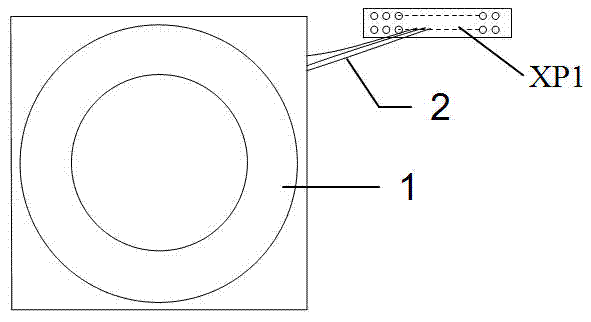
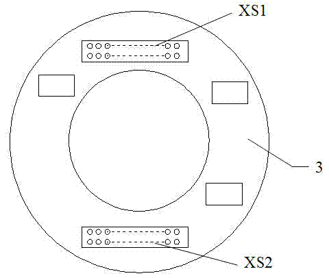
  • Motor speed measurement sensor
  • Motor speed measurement sensor
  • Motor speed measurement sensor

Examples


Embodiment Construction

[0017] The present invention will be described in further detail below in conjunction with the accompanying drawings and specific embodiments.

[0018] The output signal of the resolver is a two-phase quadrature analog signal, and their amplitude varies with the rotation angle as sine and cosine. The RDC resolver circuit measures the angle of rotation by calculating the amplitude of the output signal of the resolver. Every time the rotating shaft of the unipolar resolver rotates one revolution, the output sine and cosine signals change one revolution, and the position calculated by the RDC resolver also changes. One cycle, such as a 12-bit RDC resolver, when the rotary shaft of a unipolar resolver rotates one cycle, the output data of the 12-bit RDC resolver changes from 0 to 4096; The cosine signal changes for several cycles according to the number of pole pairs. For example, for a 4-pole resolver, when the rotating shaft rotates once, the amplitude of the output sine and cos...


PUM


Abstract

The invention provides a high-precision speed measurement sensor which is applied to a motor drive control system. The sensor comprises a multipolar resolver, an excitation power supply, an RDC (resolver-to-digital converter) solver circuit, a computing module and an output drive circuit, wherein the excitation power supply, the RDC solver circuit, the computing module and the output drive circuit are printed on the same circuit board; the excitation power supply is connected with the RDC solver circuit; the excitation power supply and the RDC solver circuit are connected with the multipolar resolver through a lead; the RDC solver circuit is connected with the computing module through a printed circuit; the computing module is connected with the output drive circuit through the printed circuit; and the output drive circuit is connected with the lead to send out the final result (to a motor controller). The sensor provided by the invention is of a simple structure and can improve the minimum resolution of the motor speed measurement by 4 times, 8 times, 16 times and the like according to the needs.

Description

technical field [0001] The invention relates to a high-precision speed measuring sensor, which is applied in the technical field of motor drive control systems. Background technique [0002] In motor control systems, speed measurement is essential. At present, there are mainly three methods to measure the speed of the motor: [0003] 1. Tachogenerator method: Use the relationship that the armature voltage of the tachogenerator is proportional to the speed to measure the speed. When measuring the speed, the tachometer generator is connected to the shaft end of the motor under test, and the mechanical speed of the motor under test is converted into a voltage signal output, and the motor control system performs signal conditioning on the output voltage of the tachometer generator for analog-digital conversion (AD conversion ), so as to measure the speed of the motor. [0004] 2. Photoelectric code disc speed measurement method: it is a speed measurement method to measure th...

Claims


Application Information

Patent Timeline
Patent Type & Authority Patents(China)
IPC IPC(8): G01P3/481
Inventor 陈桂李宏胜盛党红林健
Owner NANJING INST OF TECH
Learn More